Switch 1
Switch 2
Switch 3

PAGE 26

06 Apr 2000

CH. 4: TIU110/111/112/113

GFK-1819


4.5.1TIU11X Configuration of the RS-485 Port

The configuration bank (shown in Figure 4.8) sets the parameters of the RS-485 port as described in Table 4.1.

Table 4.1 – Configuration Bank

ON: Pull-up (must be used together with switch 3)

OFF: no Pull-up

ON: 120termination

OFF: no termination

ON: Pull-down (must be used together with switch 1)

OFF: no Pull-down

Switch 4Reserved for future use

NOTE: Switch 1 and 3 must be used together. Either both pull-up and pull-down are used or neither is used.

Pull-upand Pull-downswitches are used to increase the signal level on the RS-485 bus. This is useful if there is a long bus and a significant amount of attenuation is anticipated.

Termination resistance of 120must be placed across each end of the RS-485 bus. With switch 2 ON, a 120resistance is placed across the bus. This should only be used if the TIU050/100/110 is the last device at either end of the bus.

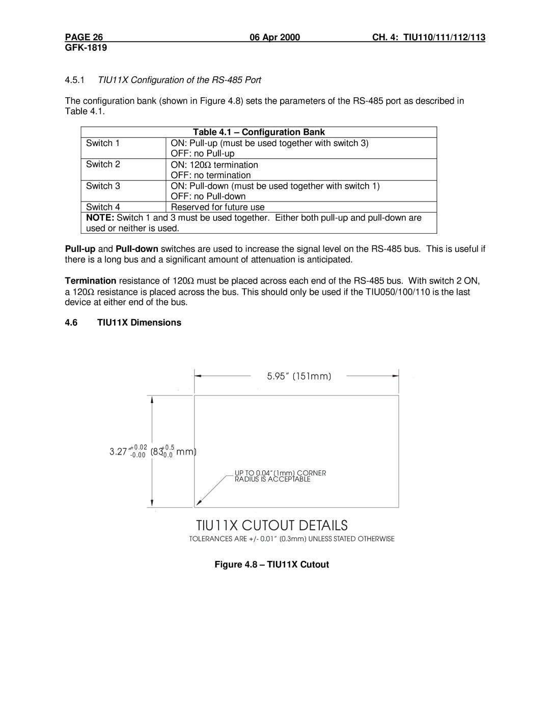
4.6TIU11X Dimensions

5.95” [151mm]

3.27”+-00.0.002[83+-00.0.5mm]

UP TO 0.04”[1mm] CORNER

RADIUS IS ACCEPTABLE

TIU11X CUTOUT DETAILS

TOLERANCES ARE +/- 0.01” [0.3mm] UNLESS STATED OTHERWISE

Figure 4.8 – TIU11X Cutout

Page 25
Image 25
GE IC300TIU111 manual Apr CH TIU110/111/112/113 GFK-1819, 1 TIU11X Configuration of the RS-485 Port, TIU11X Dimensions