PAGE 22 | 06 Apr 2000 | CH.3: TIU100/101/102/103 |
|
|
|
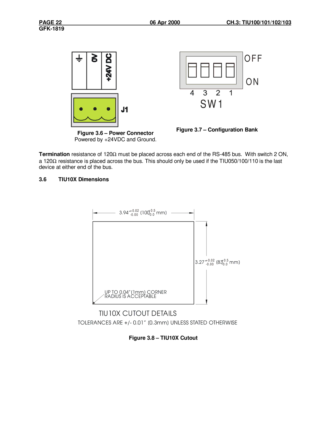
Figure 3.6 – Power Connector Powered by +24VDC and Ground.
O F F
O N
S W 1
Figure 3.7 – Configuration Bank
Termination resistance of 120Ω must be placed across each end of the
3.6TIU10X Dimensions
UP TO 0.04”[1mm] CORNER ![]() RADIUS IS ACCEPTABLE
RADIUS IS ACCEPTABLE
+ 0 .0 2 | + 0 .5 | mm] |
3.27” | [83 | |
|
TIU10X CUTOUT DETAILS
TOLERANCES ARE +/- 0.01” [0.3mm] UNLESS STATED OTHERWISE