PAGE 42 | 06 Apr 2000 | CH. 8: NETWORKS |
|
|
| R x D |
|
| R x D |
|
|
|
| R x D |
| R x D |
|
|
|
|
|
|
| R x D |
|
| R x D | ||||||||
| /T xD | D G N D | V + | / T x D |
|
|
|
| D G N D /T xD | V + | / T x D |
|
|
|
|
|
|
| /T xD | D G N D | V + | / T x D | ||||||||
8 | 5 | 6 | 3 |
| 5 8 | 6 | 3 |
| 8 | 5 | 6 | 3 |
| |||||||||||||||||
|
|
|
|
|
|
|
|
|
|
|
|
|
|
|
|
|
|
|
|
|
|
|
|
|
|
|
|
|
|
|
|
|
|
|
|
|
|
|
|
|
|
|
|
|
|
|
|
|
|
|
|
|
|
|
|
|
|
|
|
|
|
|
|
|
|
|
|
|
|
|
|
|
|
|
|
|
|
|
|
|
|
|
|
|
|
|
|
|
|
|
|
|
|
|
|
|
|
|
|
|
|
|
|
|
|
|
|
|
|
|
|
|
|
|
|
|
|
|
|
|
|
|
|
|
|
|
|
|
|
|
|
|
|
|
|
|
|
|
|
|
|
|
|
|
|
|
|
|
|
|
|
|
|
|
|
|
|
|
|
|
|
|
|
|
|
|
|
|
|
|
|
|
|
|
|
|
|
|
|
|
|
|
|
|
|
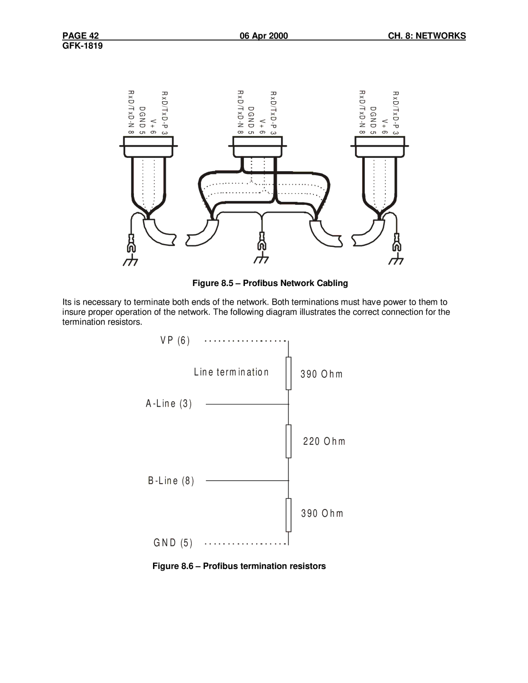
Figure 8.5 – Profibus Network Cabling
Its is necessary to terminate both ends of the network. Both terminations must have power to them to insure proper operation of the network. The following diagram illustrates the correct connection for the termination resistors.
V P (6 )
L in e term in atio n
3 90 O h m
A
2 20 O h m
B
3 90 O h m
G N D (5 )