CH. 7: GETTING STARTED | 06 Apr 2000 | PAGE 35 | |
|
|
| |
CHAPTER 7: GETTING STARTED
7.1Self-Test
Power up the unit with the UP and ENTER keys pressed at the same time. The unit enters a
7.1.1Contrast Band
This test allows the user to set the lower and upper limits of contrast. Adjust the lower limit using the UP or DOWN key and press Enter when done. Do the same for the upper limit.
WARNING: - Changes to the lower or upper limits may allow the user to set the contrast to a setting where the display may appear blank. It is recommended that the factory setting are used (Min 8A, Max FE).
7.1.2Display Test
The display test continuously blinks all pixels on (black) to off. Look for any pixels stuck on or off. Exit this test by pressing and holding any key for approximately two seconds.
7.1.3Keyboard Test
As each key is pressed, an indication *** appears above that key. In the case of units with a numeric keypad, press the key and a message appears indicating the key press. Check for keys indicating multiple presses or not reporting presses. Exit this test by pressing and holding any key for approximately two seconds.
7.1.4RAM Test
Test either segment 0000 or segment 1000 (on the TIU100/110) of the RAM. The segment 1000 test performs a base 3 repeating test. This test detects shorted address lines and damaged memory bits. The segment 0000 test performs a
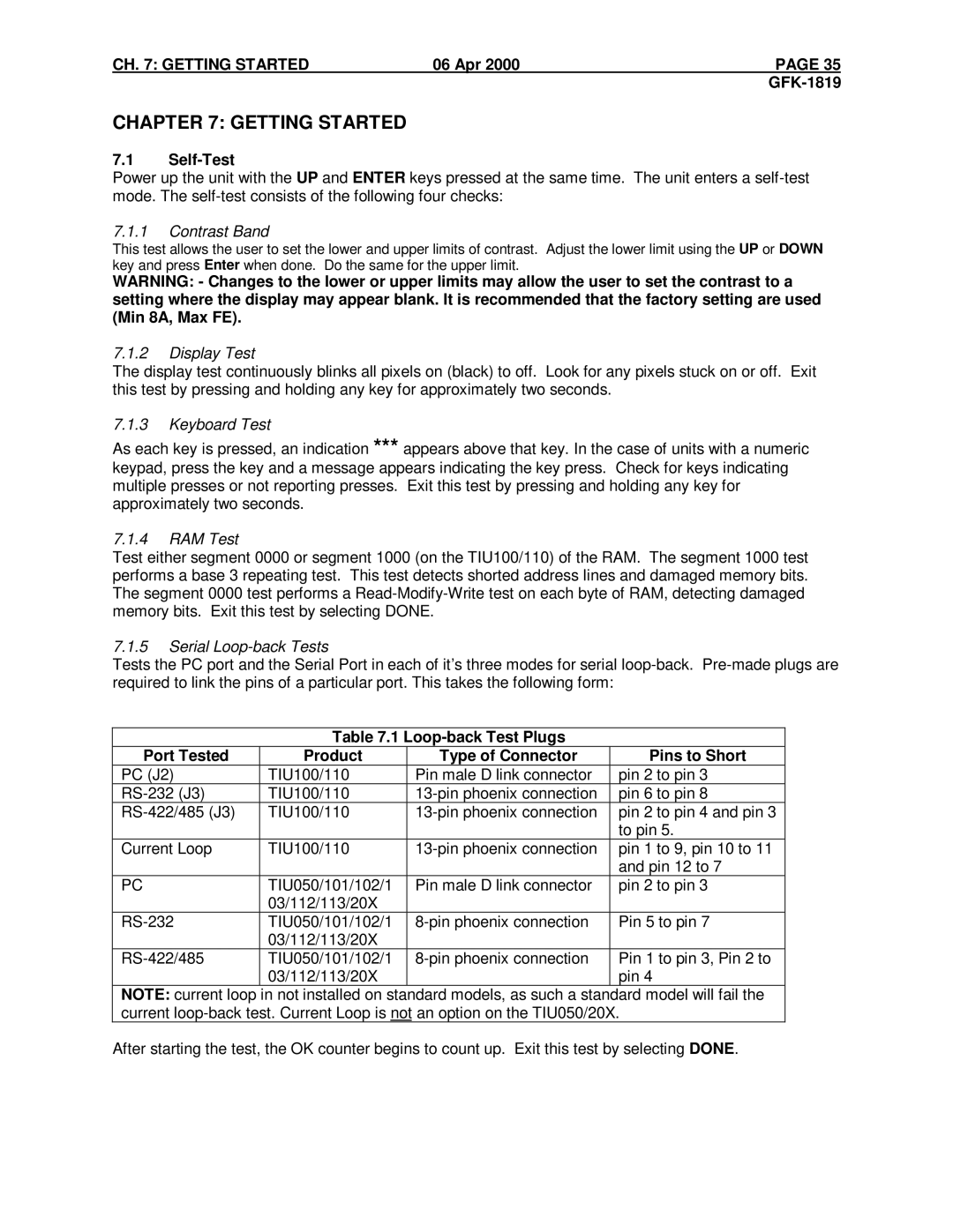
7.1.5Serial Loop-back Tests
Tests the PC port and the Serial Port in each of it’s three modes for serial
Table 7.1
Port Tested | Product | Type of Connector | Pins to Short |
PC (J2) | TIU100/110 | Pin male D link connector | pin 2 to pin 3 |
TIU100/110 | pin 6 to pin 8 | ||
TIU100/110 | pin 2 to pin 4 and pin 3 | ||
|
|
| to pin 5. |
Current Loop | TIU100/110 | pin 1 to 9, pin 10 to 11 | |
|
|
| and pin 12 to 7 |
PC | TIU050/101/102/1 | Pin male D link connector | pin 2 to pin 3 |
| 03/112/113/20X |
|
|
TIU050/101/102/1 | Pin 5 to pin 7 | ||
| 03/112/113/20X |
|
|
TIU050/101/102/1 | Pin 1 to pin 3, Pin 2 to | ||
| 03/112/113/20X |
| pin 4 |
NOTE: current loop in not installed on standard models, as such a standard model will fail the current
After starting the test, the OK counter begins to count up. Exit this test by selecting DONE.