PREWRE THE OPENING (continued)
Flooring Under the Range
Your range, like many other household items, is heavy and can settle into soft floor coverings such as cushioned vinyl or carpeting. When moving the range on this type of flooring, use care, and follow these simple and inexpensive instructions.
The range should be installed on a 1/4 inch thick sheet of plywood (or similar material) as follows:
When the floor covering ends at the fhont of the range, the area that the range will rest on should be built up with plywood to the same level or higher than the floor covering. This will allow the range to be moved for cleaning or servicing.
STEP 2
PREIMRE FOR ELECTRICAL CONNECTION
Use only a
The electrical rating of the cord must be 125/250 volts minimum, 40 amperes.
NOTE: Only a
STEP 3
1.Locate connector block at the bottom rear of range and remove rear wiring cover.
2.Directly below the connector block is a hole with a knockout ring for accommodating conduit fittings. Brackets provided are used to support the flexible cord strain relief, which must be securely attached to the cord set.
TOR
STRAIN RELIEF (PROVIDED WIT SET NOT PART
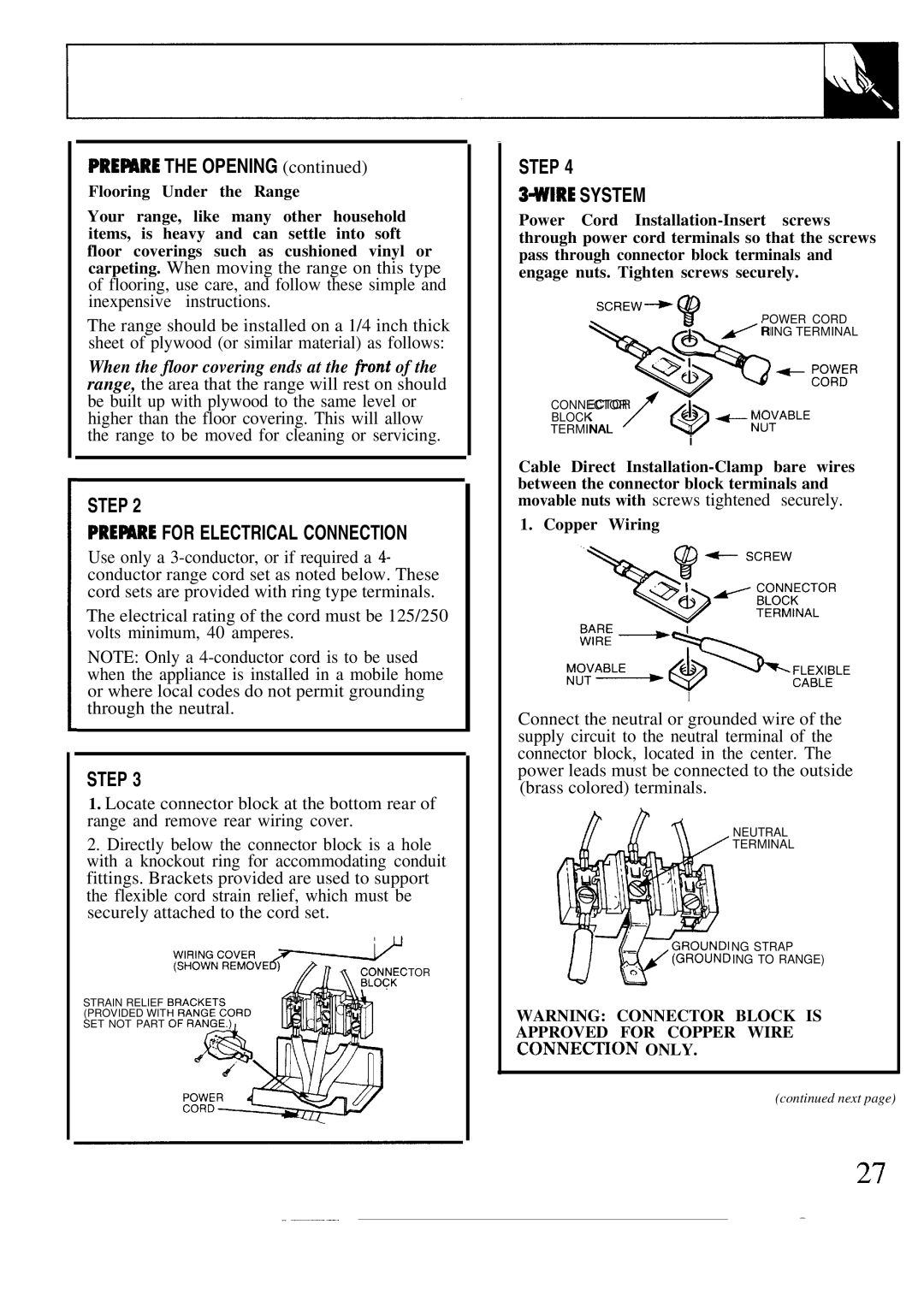
STEP 4
3+UIRE SYSTEM
Power Cord
SCREW+
$?POWER CORD &/ RING TERMINAL
e+ ::~:R
>?&
CONNECTOR
BLOCK~ ~4:ABLE
TERMINAL
i
Cable Direct
1. Copper Wiring
I
Connect the neutral or grounded wire of the supply circuit to the neutral terminal of the connector block, located in the center. The power leads must be connected to the outside (brass colored) terminals.
NEUTRAL
TERMINAL
NG STRAP
ING TO RANGE)
WARNING: CONNECTOR BLOCK IS APPROVED FOR COPPER WIRE CONNECI’ION ONLY.
(continued next page)
27
— |
| — |
|