INSTALLATION INSTRUCTIONS
(continued)
PREPARE THE OPENING (cent’d)
Flooring lJnder the Range
Your range, like many other household items, is heavy and can settle into soft
floor coverings such as cushioned vinyl or carpeting. When moving the range on this type of flooring, it should be installed on a 1/4 inch thick sheet of plywood (or similar material) as follows:
When the floor covering ends at the front of the range, the area that the range will rest on should be built up with plywood to the same level or higher than the floor covering. This will allow
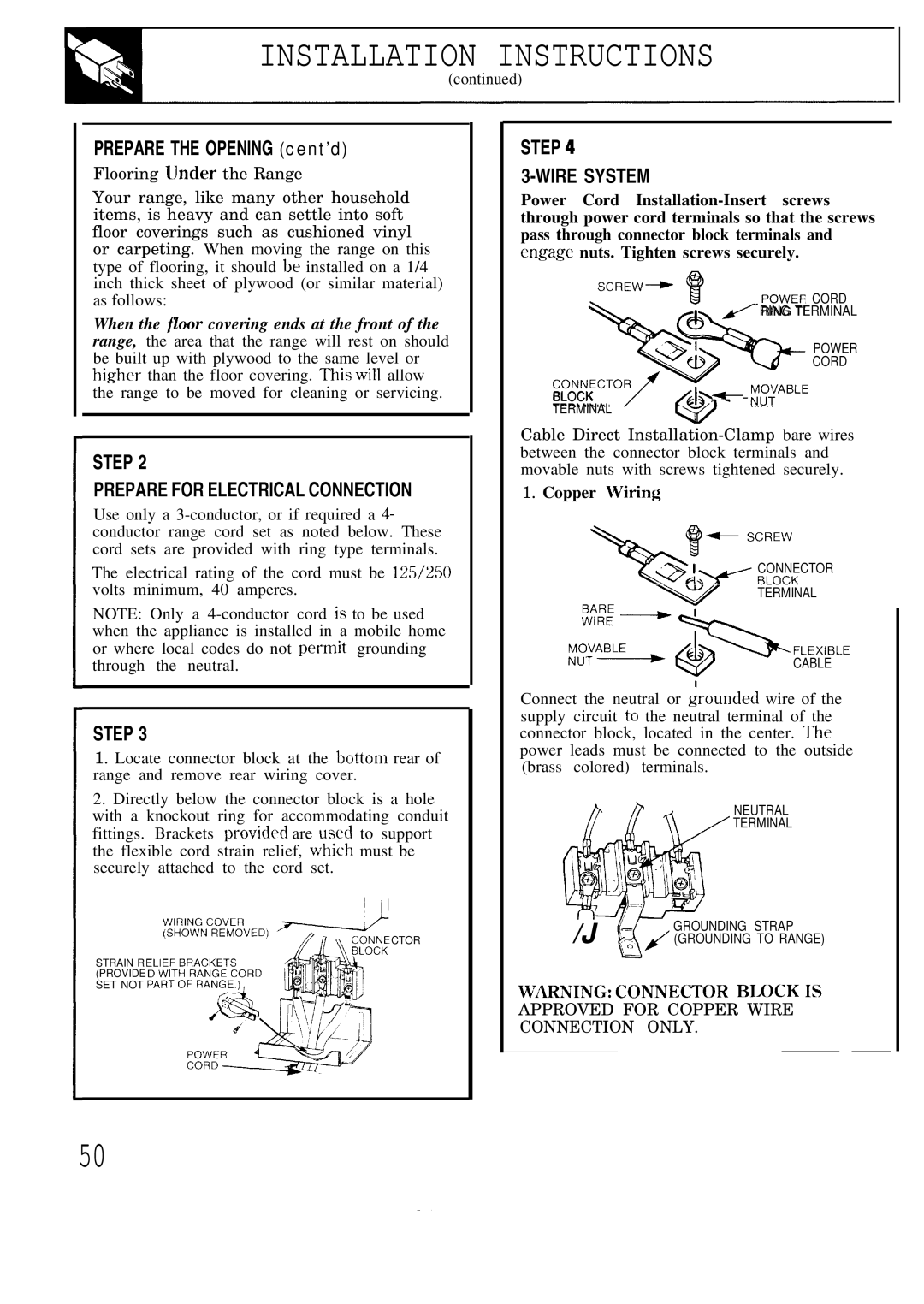
STEP 4
3-WIRE SYSTEM
Power Cord
+
SCREW+
POWER CORD
# RING TERMINAL
&
POWER
.oNN&L CORD
the range to be moved for cleaning or servicing.
BLOCK TERMINAL
~ - )j:.IABLE
STEP 2
PREPARE FOR ELECTRICAL CONNECTION
Use only a
The electrical rating of the cord must be 1251250 volts minimum, 40 amperes.
NOTE: Only a
STEP 3
1.Locate connector block at the bottom rear of range and remove rear wiring cover.
2.Directly below the connector block is a hole with a knockout ring for accommodating conduit fittings. Brackets provicled are used to support the flexible cord strain relief, which must be securely attached to the cord set.
CTOR
STRAIN R (PROVIDE SET NOT
@
Cable Direct
1.Copper Wiring
CONNECTOR
TERMINAL
CABLE
Connect the neutral or ~rounded wire of the supply circuit to the neutral terminal of the connector block, located in the center. The power leads must be connected to the outside (brass colored) terminals.
NEUTRAL
TERMINAL
/J (& GROUNDING STRAP (GROUNDING TO RANGE)
w~ING: coNNJ7~OR BLOCK Is
APPROVED FOR COPPER WIRE
CONNECTION ONLY.
50