Step 7
Install 1/2″ Flexible Conduit with Supplied
Clamp
NOTE: A clamp |
|
|
has been |
|
|
included with |
|
|
the cooktop for | Clamp |
|
installing the |
| |
|
| |
1/2″ flexible | Stop Tab |
|
conduit. |
|
|
| Clamping | Clamping |
| Screw | |
| Tab | |
|
|
Remove the screws holding the wire compartment cover and remove the cover.
Remove the clamping screw and the clamp.
Feed the power | Power Supply | |
supply leads | Leads | Bushing |
|
| |
through the |
|
|
conduit; be sure |
|
|
to leave enough |
|
|
length to |
|
|
properly | Bushing (Fully Seated) | |
connect these | ||
leads to the |
|
|
cooktop power |
|
|
leads. |
|
|
Thread the leads through an
Feed the leads
through the hole in the wire compartment.
Lay the conduit against the side of the wire compartment.
Place the clamp |
| |
over the |
| |
conduit. Make |
| |
sure the | Clamp | |
bushing is fully | ||
| ||
seated against | Stop Tab | |
the stop tab in |
| |
the clamp. | Clamping | |
| Tab |
Tighten the
clamping screw ![]()
![]()
![]()
![]()
![]()
![]()
![]() until the
until the![]()
![]()
![]()
![]()
![]()
![]() clamping tab is
clamping tab is![]()
![]()
![]()
![]()
![]()
![]() fully seated
fully seated![]()
![]()
![]()
![]()
![]()
![]()
![]() against the wire Clamping
against the wire Clamping ![]()
![]()
compartment. Screw
Clamping
Tab
Complete the rest of the installation observing local codes (see Steps 9 and 10).
When complete reinstall the wire compartment cover.
Step 8
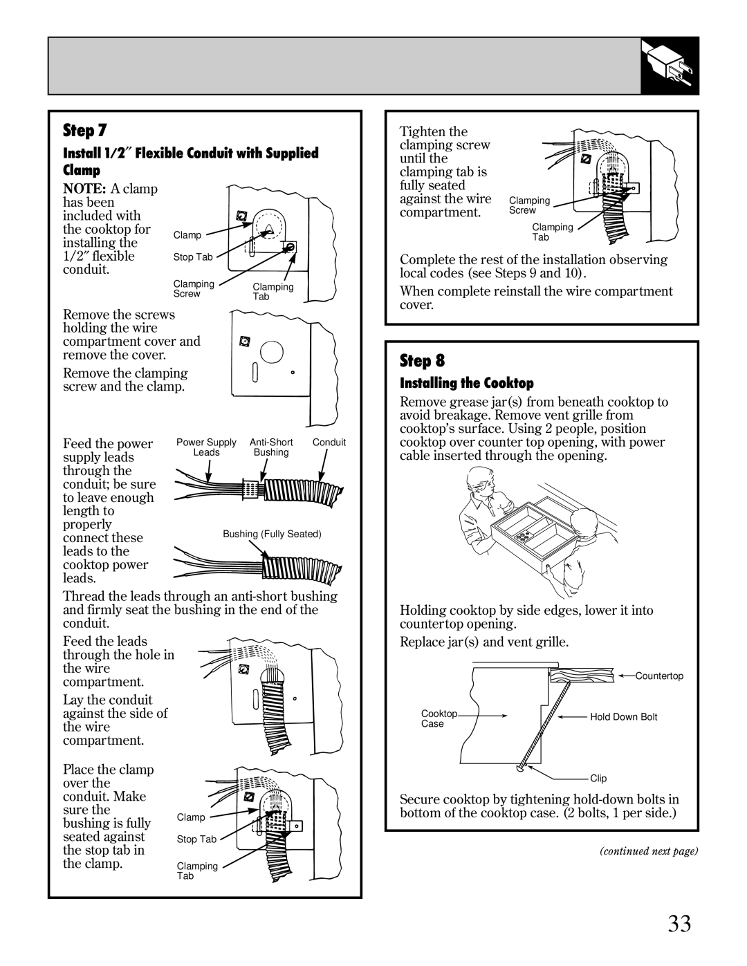
Installing the Cooktop
Remove grease jar(s) from beneath cooktop to avoid breakage. Remove vent grille from cooktop’s surface. Using 2 people, position cooktop over counter top opening, with power cable inserted through the opening.
Holding cooktop by side edges, lower it into countertop opening.
Replace jar(s) and vent grille.
![]()
![]() Countertop
Countertop
Cooktop | Hold Down Bolt | |
Case | ||
| ||
| Clip |
Secure cooktop by tightening
(continued next page)
33