INSTALLATION INSTRUCTIONS
(continued)
Step 9
Before Making Electrical Connections
Note to Electrician: The power leads supplied with this appliance are U. L. recognized for connection to large gauge household wiring. The insulation of these leads is rated at temperatures much higher than the temperature rating of household wiring. The current carrying capacity of a conductor is governed by the wire gauge and also the temperature rating of the insulation around the wire.
Aluminum
Attach copper wires to aluminum wiring using special connectors designed and U. L. listed for joining copper to aluminum. Follow the connector manufacturer’s recommended procedure closely.
Step 10
Making Electrical Connections
NOTE: The frame of this appliance is grounded to neutral.
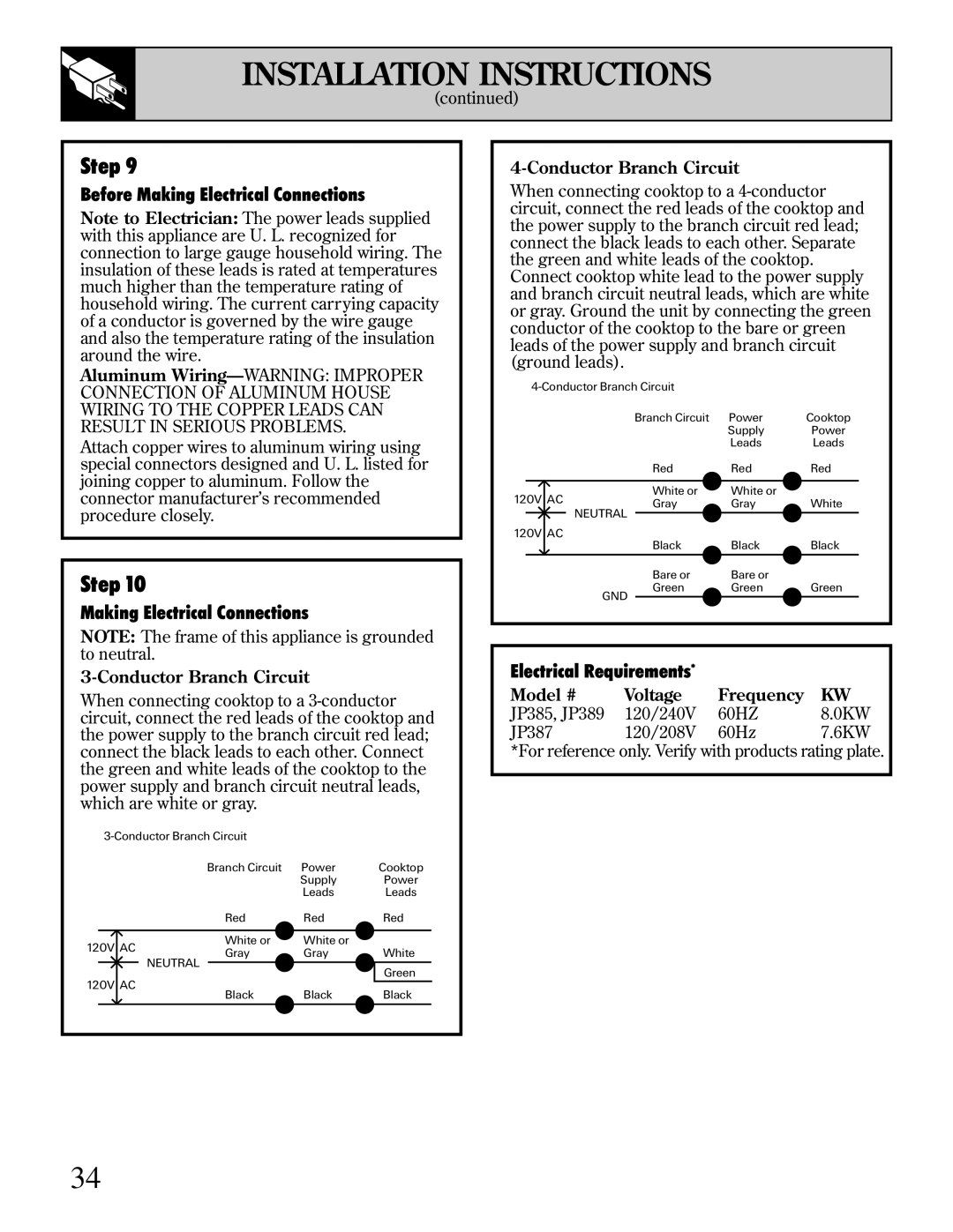
3-Conductor Branch Circuit
When connecting cooktop to a
Branch Circuit Power | Cooktop |
Supply | Power |
Leads | Leads |
| Red | Red | Red | |
120V AC | White or | White or |
| |
Gray | Gray | White | ||
| ||||
| NEUTRAL |
| Green | |
120V AC |
|
| ||
Black | Black | Black | ||
|
When connecting cooktop to a
Branch Circuit Power | Cooktop |
Supply | Power |
Leads | Leads |
| Red | Red | Red |
120V AC | White or | White or |
|
Gray | Gray | White | |
| NEUTRAL |
|
|
120V AC | Black | Black | Black |
|
| Bare or | Bare or |
| |
| Green | Green | Green | |
GND | ||||
|
|
| ||
|
|
|
|
Electrical Requirements*
Model # | Voltage | Frequency | KW |
JP385, JP389 | 120/240V | 60HZ | 8.0KW |
JP387 | 120/208V | 60Hz | 7.6KW |
*For reference only. Verify with products rating plate.
34