Manuals
/
GE
/
Kitchen Appliance
/
Microwave Oven
GE
JVM2070_H
manual
Smart Board, CN01 - Ribbon connector, CN03 - Vent Blower Connector, CN05
Models:
JVM2070_H
1
23
33
33
Download
33 pages
34.68 Kb
20
21
22
23
24
25
26
27
Troubleshooting
Install
Error codes
Wiring Diagram
Warranty
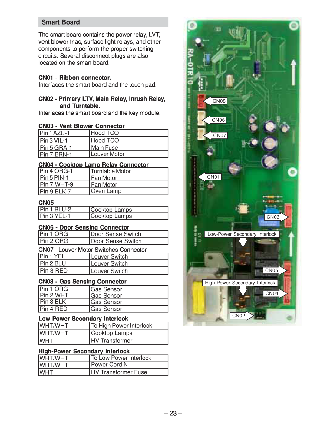
CN01 - Ribbon connector
Removal and Replacement
Safety
Power Relay
Technical Service Guide
Page 23
Image 23
Page 22
Page 24
Page 23
Image 23
Page 22
Page 24
Contents
Over the Range Microwave Oven MODEL SERIES JVM2070H
PUB #
2/04
TECHNICAL SERVICE GUIDE
GE Consumer & Industrial
IMPORTANT SAFETY NOTICE
Technical Service Guide Copyright
RECONNECT ALL GROUNDING DEVICES
A. DO NOT OPERATE OR ALLOW THE OVEN TO BE OPERATED WITH THE DOOR OPEN
Table of Contents
Model Number
Installation
Feature Pack
Nomenclature
HOME
Control Features
Touchscreen Display
HELP
Top View
Component Locator Views
4 - Magnetron Cooling Fan Motor and Blade 5 - High Voltage Capacitor
Right Side View
1 - Magnetron 2 - Magnetron Thermal Cutout TCO
3 - High Voltage Transformer
Removal
Microwave Removal and Component Access
Components
Exhaust Fan
Side Stirrer
Side Stirrer Motor
Top Stirrer
Top Stirrer Motor
Cooling Fan and Motor
Fuses
Cavity Thermal Cutout TCO
Magnetron Thermal Cutout TCO
Transformer
Magnetron
Gas Sensor
Interior Light
Hidden Vent Motor
Control Panel
Door Interlock Switches
Door Sensing and Primary Interlock Switches
Monitor Switch
Primary Interlock Switch Test
Interlocks Door Latch Switches
Door Sensing Switch
Power Relay
Turntable Motor
Removal and Replacement
High Voltage Capacitor
Bottom and Hood Thermal Cutout TCO
Surface Lamps
Surface Lamp Assemblies
Sensor Test Quick Test
Troubleshooting
Control Performance Test
Displayed Information
Diagnostics Test
Error Message
Demonstration Mode
High Voltage Capacitor
Microwave Leakage Test
Performance Test
CN06 - Door Sensing Connector
CN01 - Ribbon connector
CN03 - Vent Blower Connector
CN04 - Cooktop Lamp Relay Connector
Fan Motor Does Not Work
Strip Circuits
Louver Motor Does Not Work Vent Motor Does Not Work
FAN MOTOR
Top Stirrer, Side Stirrer, or Drive Motor Does Not Work
Dead Unit - Cavity or Magnetron TCO Does Not Work
Dead Unit - Bottom TCO Does Not Work
Interior Light Does Not Work Surface Lamps Do Not Work
Black
Magnetron Does Not Work
2 - White
3 - Blue
WARNING Power must be disconnected before servicing this appliance
Wiring Diagram
Code No. DE99-00125F
Schematic
Illustrated Parts Catalog
QUANTITY
VIEW NUMBER
CATALOG NUMBER
DESCRIPTION
PLATE MOUNTING ASM
Full one-year
Warranty
For the period of
GE will replace
Top
Page
Image
Contents