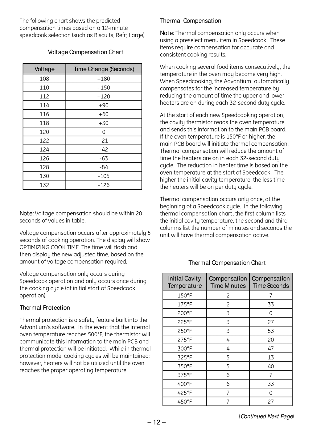
The following chart shows the predicted compensation times based on a 12-minute speedcook selection (such as Biscuits, Refr; Large).

Voltage Compensation Chart

Voltage

Time Change (Seconds)


108

+180

110

+150

112

+120

114

+90

116

+60

118

+30

120

0

122

-21

124

-42

126

-63

128

-84

130

-105

132

-126


Note: Voltage compensation should be within 20 seconds of values in table.

Voltage compensation occurs after approximately 5 seconds of cooking operation. The display will show OPTIMIZING COOK TIME. The time will flash and then display the new adjusted time, based on the amount of voltage compensation required.

Voltage compensation only occurs during Speedcook operation and only occurs once during the cooking cycle (at initial start of Speedcook operation).

Thermal Protection

Thermal protection is a safety feature built into the Advantium’s software. In the event that the internal oven temperature reaches 500°F, the thermistor will communicate this information to the main PCB and thermal protection will be initiated. While in thermal protection mode, cooking cycles will be maintained; however, heaters will not be utilized until the oven reaches the proper operating temperature.

Thermal Compensation

Note: Thermal compensation only occurs when using a preselect menu item in Speedcook. These items require compensation for accurate and consistent cooking results.

When cooking several food items consecutively, the temperature in the oven may become very high. When Speedcooking, the Advantium automatically compensates for the increased temperature by reducing the amount of time the upper and lower heaters are on during each 32-second duty cycle.

At the start of each new Speedcooking operation, the cavity thermistor reads the oven temperature and sends this information to the main PCB board. If the oven temperature is 150°F or higher, the main PCB board will initiate thermal compensation. Thermal compensation will reduce the amount of time the heaters are on in each 32-second duty cycle. The reduction in heater time is based on the oven temperature at the start of Speedcook. The higher the initial cavity temperature, the less time the heaters will be on per duty cycle.

Thermal compensation occurs only once, at the beginning of a Speedcook cycle. In the following thermal compensation chart, the first column lists the initial cavity temperature, the second and third columns list the number of minutes and seconds the unit will have thermal compensation active.

Thermal Compensation Chart

Initial Cavity

Compensation

Compensation

Temperature

Time Minutes

Time Seconds


150°F

2

7

175°F

2

33

200°F

3

0

225°F

3

27

250°F

3

53

275°F

4

20

300°F

4

47

325°F

5

13

350°F

5

40

375°F

6

7

400°F

6

33

425°F

7

0

450°F

7

27

(Continued Next Page)

– 12 –

Page 12
Image 12
GE ZSC 1001, ZSC 1000, SCB 1001, SCB 1000 manual Voltage Compensation Chart, Thermal Protection, Thermal Compensation

SCB 1000, SCB 1001, ZSC 1000, ZSC 1001 specifications

The GE ZSC 1001, ZSC 1000, SCB 1001, and SCB 1000 are cutting-edge solutions in the realm of electrical substations, designed to enhance efficiency, reliability, and safety in power management systems. These devices are integral for utilities seeking to modernize their infrastructures while maintaining optimal performance.

The GE ZSC 1000 series includes both the ZSC 1000 and ZSC 1001 models. These digital relays are renowned for their sophisticated protection and control capabilities. One of the standout features of the ZSC 1001 is its enhanced communication technology, enabling seamless integration with various systems and allowing for real-time data exchange. This model offers advanced protection functions, including overcurrent, distance, and differential protection, which are essential for safeguarding electrical assets.

The ZSC 1000 series is built on a modular architecture, facilitating easy upgrades and customization to meet specific operational needs. It employs intelligent data analysis to help operators predict equipment failures before they happen, ultimately minimizing downtime and maintenance costs. Additionally, the devices boast user-friendly interfaces that simplify monitoring and control tasks.

The SCB 1000 and SCB 1001 are also key players in GE's portfolio, tailored for busbar protection and automation. These models feature high-accuracy current sensing technology and extensive programmable parameters to suit diverse applications. Their design allows for robust performance in harsh environments, making them ideal for substations.

Both SCB models utilize advanced digital signal processing (DSP) technologies, which enhance their performance and improve the reliability of measurements. The SCB 1001 takes a step further by incorporating security measures to protect against cyber threats, ensuring the integrity of data within the grid.

In terms of interoperability, all four models support various communication protocols, facilitating better connectivity and integration with existing infrastructure. They are designed to operate seamlessly in conjunction with SCADA systems, enabling comprehensive monitoring and control functions.

To summarize, the GE ZSC 1001, ZSC 1000, SCB 1001, and SCB 1000 exemplify modern innovations in electrical protection and control. They offer a blend of advanced technologies, modular designs, and robust performance characteristics, making them invaluable assets for any utility looking to enhance its power management systems. These devices not only meet the current demands of the energy sector but are also equipped to adapt to future challenges in the evolving landscape of electrical distribution and management.