Section 4 — Maintenance
Guardian
F. EVERY 800 OPERATING HOURS
1.Retorque cylinder head (see torque specs).
2.Retorque intake and exhaust manifold (see torque specs).
3.Check engine compression.
4.Check valve clearance.
4.2EXHAUST MANIFOLD PROCEDURE
1.If necessary, clean gasket surfaces on exhaust manifold and cylinder head.
2.Install exhaust manifold and exhaust manifold gasket.
3.Install fasteners.
NOTE:
Exhaust manifold fasteners must be tightened in two stages.
4.Tighten fasteners to
5.Retighten fasteners to
4.3INTAKE MANIFOLD PROCEDURE
1.Clean and inspect the mounting surfaces of the intake manifold and the cylinder head. Both sur- faces must be clean and flat (Figure 4.1).
2.Clean and lightly oil the manifold bolt/stud threads.
3.Install a new lower intake manifold gasket.
4.Position the lower intake manifold to the cylinder head.
5.Install retaining bolts/studs finger tight.
6.Tighten all bolts/studs to specifications in the tightening sequence shown:
•First pass = 7=10
•Final pass =
Figure 4.1 — Intake Manifold Installation
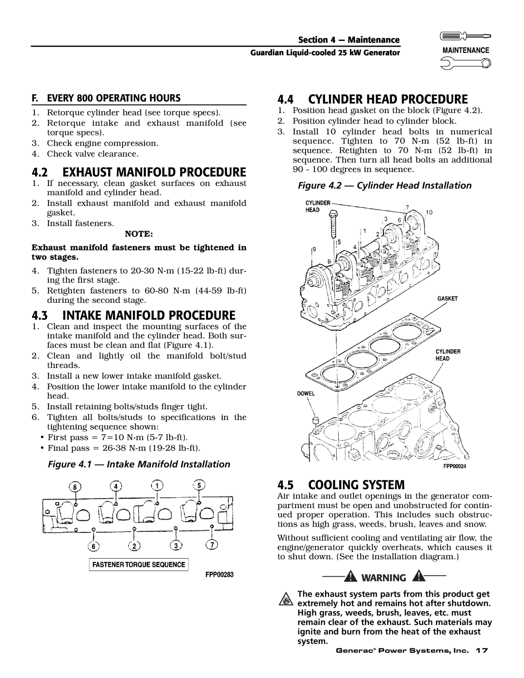
4.4CYLINDER HEAD PROCEDURE
1.Position head gasket on the block (Figure 4.2).
2.Position cylinder head to cylinder block.
3.Install 10 cylinder head bolts in numerical sequence. Tighten to 70
Figure 4.2 — Cylinder Head Installation
4.5COOLING SYSTEM
Air intake and outlet openings in the generator com- partment must be open and unobstructed for contin- ued proper operation. This includes such obstruc- tions as high grass, weeds, brush, leaves and snow.
Without sufficient cooling and ventilating air flow, the engine/generator quickly overheats, which causes it to shut down. (See the installation diagram.)
The exhaust system parts from this product get extremely hot and remains hot after shutdown. High grass, weeds, brush, leaves, etc. must remain clear of the exhaust. Such materials may ignite and burn from the heat of the exhaust system.
Generac® Power Systems, Inc. 17