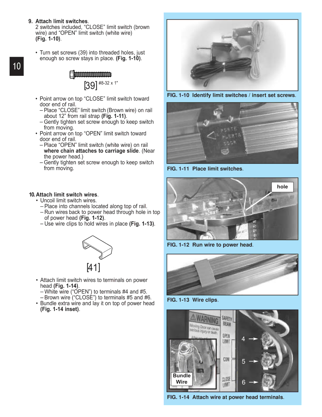
9.Attach limit switches.
2 switches included, “CLOSE” limit switch (brown wire) and “OPEN” limit switch (white wire)
(Fig.
•Turn set screws (39) into threaded holes, just enough so screw stays in place. (Fig.
10
[39]
•Point arrow on top “CLOSE” limit switch toward door end of rail.
–Place “CLOSE” limit switch (Brown wire) on rail about 12” from rail strap (Fig.
–Gently tighten set screw enough to keep switch from moving.
•Point arrow on top “OPEN” limit switch toward door end of rail.
–Place “OPEN” limit switch (white wire) on rail where chain attaches to carriage slide. (Near the power head.)
–Gently tighten set screw enough to keep switch from moving.
10.Attach limit switch wires.
•Uncoil limit switch wires.
–Place into channels located along top of rail.
–Run wires back to power head through hole in top of power head (Fig.
–Use wire clips to hold wires in place (Fig.
FIG. 1-10 Identify limit switches / insert set screws.
FIG. 1-11 Place limit switches.
hole
[41]
•Attach limit switch wires to terminals on power head (Fig.
–White wire (“OPEN”) to terminals #4 and #5.
–Brown wire (“CLOSE”) to terminals #5 and #6.
•Bundle extra wire and lay it on top of power head (Fig.
FIG. 1-12 Run wire to power head.
FIG. 1-13 Wire clips.
|
|
|
| 4 |
|
|
|
| |
|
|
|
| 5 |
|
|
|
|
|
|
| Bundle |
|
|
|
| Wire |
| 6 |
|
|
|
|
|
|
|
|
|
|