2 INSTALLATION | FOR |
I M P O R TA N T
![]() WARNING :
WARNING :
To reduce the risk of severe injury or death:
11
1.READ AND FOLLOW ALL SAFETY, INSTALLATION AND OPERATION INSTRUCTIONS. If you have questions or do not understand an instruction, call The Genie Company or an authorized Genie Dealer.
2.Do Not install operator on an improperly balanced door. An improperly balanced door could cause severe injury. Repairs and adjustments to cables, spring assembly, and other hardware must be made by a professionally trained service technician using proper tools and instructions.
3.Remove all ropes and disable all locks connected to the door before installing operator.
4.Install door operator 7 feet or more above floor. Mount emergency release knob 6 feet above floor.
5.Do Not connect the operator to the source of power until instructed to do so.
6.Locate the control button:
•Within sight of door.
•At minimum height of 5 feet above the highest floor level, so small children cannot reach it.
•Away from all moving parts of the door.
7.Install the Entrapment WARNING Label next to the wall button or wall console. Install the emergency release tag on, or next to, the emergency release.
8.The operator must reverse when the door contacts a
HEADER AND DOOR
MOUNTING BRACKETS:
![]() CAUTION
CAUTION
Header bracket must be fastened to garage framing. Do Not fasten to drywall, particle board, plaster or other such materials.
1. Finding header bracket mounting location. | |
• | Close garage door. |
| – Use a pencil. |
| a. Mark center of garage door |
| width) with 6” vertical line at top edge of door. |
| b. Continue this line on wall above door for |
• | about 12" (Fig. |
Raise garage door until top edge of door | |
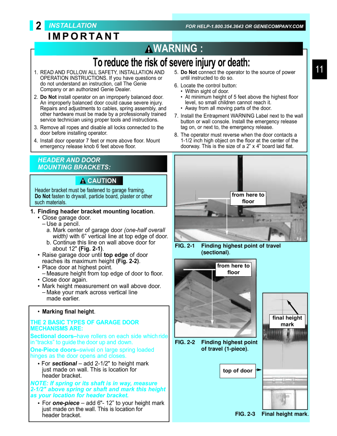
from here to
floor
FIG. 2-1 Finding highest point of travel (sectional).
reaches its maximum height (Fig. |
• Place door at highest point. |
– Measure height from top edge of door to floor. |
• Close door again. |
• Mark height measurement on wall above door. |
– Make your mark across vertical line |
made earlier. |
• Marking final height. |
THE 2 BASIC TYPES OF GARAGE DOOR MECHANISMS ARE:
Sectional
•For sectional – add
NOTE: If spring or its shaft is in way, measure
• For |
just made on the wall. This is location for |
from here to |
floor |
FIG. 2-2 Finding highest point of travel (1-piece).
top of door 
final height |
mark |
header bracket. |