8
1OPERATOR ASSEMBLY
RAIL ASSEMBLY: Use a clean, flat surface.
![]() CAUTION
CAUTION
Drive chain can slide out of rails. Do not run until operator is fully assembled.
NOTE: For
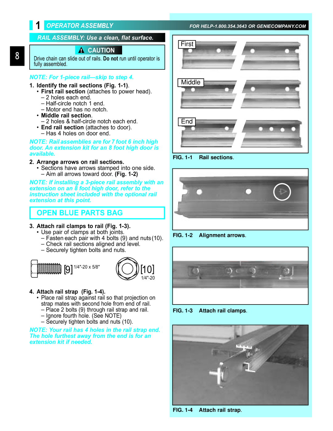
1.Identify the rail sections (Fig. 1-1).
•First rail section (attaches to power head).
–2 holes each end.
–
–Motor end has no notch.
•Middle rail section.
–2 holes &
•End rail section (attaches to door).
–Has 4 holes on door end.
NOTE: Rail assemblies are for 7 foot 6 inch high door. An extension kit for an 8 foot high door is available.
2.Arrange arrows on rail sections.
• Sections have arrows stamped into one side.
– Aim all arrows toward door. (Fig.
NOTE: If installing a
OPEN BLUE PARTS BAG
3.Attach rail clamps to rail (Fig. 1-3).
•Use pair of clamps at both joints.
–Fasten each pair with 4 bolts (9) and nuts(10).
–Check rail sections aligned and level.
–Securely tighten bolts and nuts.
[10] | |
|
4.Attach rail strap (Fig. 1-4).
•Place rail strap against rail so that projection on strap mates with second hole from end of rail.
–Place 2 bolts (9) through rail strap and rail.
–Ignore fourth hole. (See NOTE)
–Securely tighten bolts and nuts (10).
NOTE: Your rail has 4 holes in the rail strap end. The hole furthest away from the end is for an extension kit if needed.
FOR
