English
Please follow the steps below to construct a complete RAID array:
1)Have ready your hard drives for RAID construction.
Note: To achieve best performance, it is recommended that the hard drives used are of similar make and storage capacity.
2)Please attach the hard drive connectors to their appropriate location on the motherboard ie. IDE, SCSI, or SATA.
3)Enter the motherboard BIOS and locate RAID setup (Please refer to the section on Integrated Peripherals).
4)Enter RAID setup in the BIOS and select the RAID type (For instance, enter F10 to select NVIDIA RAID; Ctrl + S to select Silicon Image).
5)Complete driver installation.
6)Complete RAID utility installation.
More information on steps 4 and 5 is provided. (For more detailed setup information, please visit "Support\ Motherboard\ Technology Guide section" on our website at http:\\www.gigabyte.com.tw to read or download the information you need.)
Configuring the nVIDIA RAID BIOS
The NVRAID BIOS setup lets you choose the RAID array type and which hard drives you want to make part of the array.
Entering the RAID BIOS Setup
1.After rebooting your computer, wait until you see the RAID software prompting you to press F10. The RAID prompt appears as part of the system POST and boot process prior to loading the OS. You have a few seconds to press F10 before the window disappears.
NVIDIA RAID IDE ROM BIOS 4.60
Copyright (C) 2004 NVIDIA Corp.
Detecting array ...
Press F10 to enter RAID setup utility ...
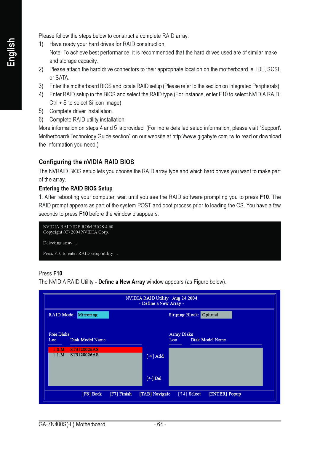
Press F10.
The NVIDIA RAID Utility - Define a New Array window appears (as Figure below).
NVIDIA RAID Utility | Aug 24 2004 |
- Define a New | Array - |
RAID Mode: Mirroring | Striping Block: Optimal | ||
Free Disks |
| Array Disks | |
Loc | Disk Model Name | Loc | Disk Model Name |
1.0.M | ST3120026AS |
|
|
1.1.M | ST3120026AS | [J] Add |
|
|
| [I] Del |
|
| [F6] Back [F7] Finish | [TAB] Navigate | [KL] Select [ENTER] Popup |
- 64 - |