Users Manual
GA-7N400S / GA-7N400S-L
Rev. 1003 12ME-7N400S-1003
Motherboard
Motherboard
GA-7N400S Oct. 18
GA-7N400S
Copyright
Product Manual Classification
Table of Contents
4-1-2
Unique Software Utilities
4-1-1
4-1-3
GA-7N400S/GA-7N400S-L Motherboard Layout
GA-7N400S
Ultra
Block Diagram
nForce
NBGCLK 66 MHz
Page
Installation Notices
Chapter 1Hardware Installation
1-1 Considerations Prior to Installation
Instances of Non-Warranty
English
1-2 Feature Summary
Additional Features
2 Serial ATA ports from nVIDIA nForceTM 2 MCP RAID SATA0, SATA1
1-3 Set System Clock CLKSW
1-4 Installation of the CPU and Heatsink
English
1-4-2 Installation of the Heatsink
1-4-1 Installation of the CPU
English
1-5 Installation of Memory
English
Dual Channel DDR
English
1-6 Installation of Expansion Cards
English
USB port
PS/2 Keyboard and PS/2 Mouse Connector
1-7 I/O Back Panel Introduction
Parallel Port
1-8 Connectors Introduction
English
1/2 ATX12V / ATX Power Connector
English
5 FDD FDD Connector
3/4 CPUFAN / SYSFAN Cooler Fan Power Connector
English
7 SATA0 / SATA1 Serial ATA Connector
6 IDE1 / IDE2 IDE Connector
English
8 PWRLED
9 BATBattery
English
English
10 FPANEL Front Panel Jumper
MSG Message LED/Power/Sleep LED
MSG+ MSG- PW+ PW
12 SURCEN Surround Center Connector
11 FAUDIO Front Audio Panel Connector
English
English
13/14 CDIN CD In Connector, black / AUXIN AUX In Connector, white
15 SPDIFIO SPDIF In / Out Connector
CDIN, black
17 IR
16 F USB1 / FUSB2 Front USB Connector
English
Open Normal
18 CLRCMOS Clear CMOS
English
Short Clear CMOS
CONTROL KEYS
Chapter 2 BIOS Setup
Status Page Setup Menu / Option Page Setup Menu
Main Menu
Advanced BIOS Features
The Main Menu For example BIOS Ver. E17
Standard CMOS Features
Advanced Chipset Features
Set User Password
Load Optimized Defaults
Set Supervisor Password
Save & Exit Setup
Time
Standard CMOS Features
Date
English
Halt on
Floppy 3 Mode Support for Japan Area
Drive A / Drive B
Memory
First / Second / Third Boot Device
Advanced BIOS Features
Hard Disk Boot Priority
Boot Up Floppy Seek
Init Display First
Password Check
English
FSB Frequency
Advanced Chipset Features
System Performance
Memory Frequency Note
On-Chip Primary PCI IDE
IDE Function Setup
Integrated Peripherals
On-Chip Secondary PCI IDE
SATA Spread Spectrum
RAID Config
SATA DMA Transfer
English
OnChip USB
UART Mode Select
UR2 Duplex Mode
USB Keyboard Support
Onboard Parallel port
Parallel Port Mode
ECP Mode Use DMA
Game Port Address
ACPI Suspend Type
Power Management Setup
Resume by Alarm
Soft-off by PWR-BTTN
KB Power ON Password
Power On by Mouse
Power On by Keyboard
AC BACK Function
PCI 3 IRQ Assignment
PnP/PCI Configurations
PCI 2 IRQ Assignment
PCI 4 IRQ Assignment
Current Voltage V Vcore / DDR25V / +3.3V / +12V
Current System/CPU Temperature
PC Health Status
Current CPU/SYSTEM FAN Speed RPM
Load Optimized DefaultsSaveY/N?& ExitN Setup
Load Fail-Safe Defaults
Load Optimized Defaults
English
2-10
Set Supervisor/User Password
English
Type Y will quit the Setup Utility without saving to RTC CMOS
2-11 Save & Exit Setup
2-12 Exit Without Saving
Type N will return to Setup Utility
English
GA-7N400S-L Motherboard
3-1 Install Chipset Drivers
Chapter 3Drivers Installation
English
3-3 Software Information
3-2 Software Application
English
English
3-4 Hardware Information
3-5 Contact Us
This page lists all device you have for this motherboard
English
GA-7N400S-L Motherboard
How to use the Xpress Recovery
4-1-1 Xpress Recovery Introduction
What is Xpress Recovery ?
Chapter 4 Appendix
Intel 865PE AGPSet BIOS for 8IPE1000MT F1 Check System Health OK
F9 For Xpress Recovery
English
2. Execute Restore Utility
1. Execute Backup Utility
Press B to Backup your System or Esc to Exit
This program will recover your system to factory default
Method 1 Q-FlashTM Utility
4-1-2 Flash BIOS Method Introduction
Updating BIOS with Q-FlashTM Utility on Dual BIOS Motherboards
Before You Begin
Entering the Q-FlashTM utility
Exploring the Q-FlashTM / Dual BIOS utility screen
Task menu for Dual BIOS utility
Task menu for Q-Flash utility
Steps
Using the Q-FlashTM utility
English
Copy BIOS completed - Pass
BIOS, too
The BIOS file becomes Fba after updating
Are you sure to RESET ?
English
Updating BIOS with Q-FlashTM Utility on Single-BIOS Motherboards
Part Two
Press Y on your keyboard to save and exit
Task menu for Q-Flash utility
Exploring the Q-FlashTM utility screen
Using the Q-FlashTM utility
Action bar
Are you sure to RESET ?
Congratulation!! You have updated BIOS successfully
Copy BIOS completed - Pass
English
1. Methods and steps
Method 2 @BIOSTM Utility
English
2. Note
English
RAID Levels
4-1-3 Serial ATA BIOS Setting Utility Introduction
English
Entering the RAID BIOS Setup
Configuring the nVIDIA RAID BIOS
English
Selecting the Striping Block Size
Using the Define a New Array Window
Selecting the RAID Mode
Assigning the Disks
Completing the RAID BIOS Setup
English
English
Array Detail
Installing the RAID drivers
English
4-1-4 2- / 4- / 6- Channel Audio Function Introduction
2 Channel Audio Setup
English
4 Channel Audio Setup
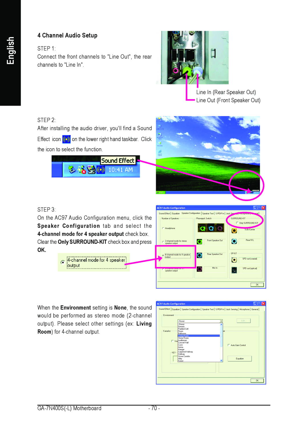
English
Basic 6 Channel Audio Setup
English
Advanced 6 Channel Audio Setup using Audio Combo Kit, optional device
English
Basic & Advanced 6 Channel Audio Output Mode Notes
English
SPDIF Output Device Optional Device
English
Auto-detecting
Introduction of audio connectors
Jack-Sensing Introduction
English
Manual setting
English
4-2 Troubleshooting
English
English
GA-7N400S-L Motherboard
Address No.6, Bau Chiang Road, Hsin-Tien, Taipei 231, Taiwan
Contact Us
English
TEL +886-2-8912-4888
English
China