INSTALLATION
WIRING DIAGRAM
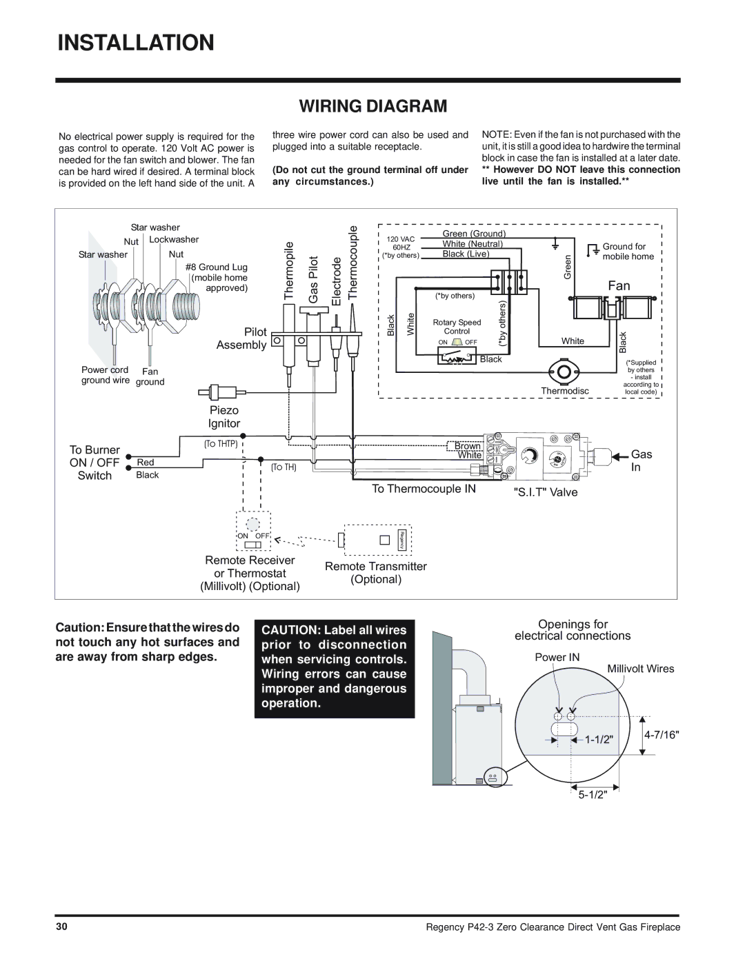
No electrical power supply is required for the gas control to operate. 120 Volt AC power is needed for the fan switch and blower. The fan can be hard wired if desired. A terminal block is provided on the left hand side of the unit. A
three wire power cord can also be used and plugged into a suitable receptacle.
(Do not cut the ground terminal off under any circumstances.)
NOTE: Even if the fan is not purchased with the unit, it is still a good idea to hardwire the terminal block in case the fan is installed at a later date.
**However DO NOT leave this connection live until the fan is installed.**
| Star washer |
| |
Nut | Lockwasher | Thermopile | |
| |||
Star washer |
| Nut | |
|
| #8 Ground Lug | |
|
| (mobile home | |
|
| approved) | |
|
|
| |
|
| Pilot |
|
|
| Assembly |
|
GasPilot | Electrode Thermocouple | ||
|
|
|
|
|
|
|
|
|
|
|
|
120VAC
60HZ
(*by others)
Black | White |
Green (Ground)
White (Neutral)
Black (Live)
(*by others) |
|
|
|
|
|
| |||
|
|
|
|
|
| ||||
|
|
|
|
|
| ||||
| others) | ||||||||
Rotary Speed |
| ||||||||
|
|
|
|
|
| ||||
| Control |
| (*by | ||||||
| ON | OFF |
|
| |||||
| Ground for |
Green | mobile home |
|
Fan
Fan |
White | Black |
|
Power cord | Fan |
| |
ground wire | ground |
| |
|
| Piezo | |
|
| Ignitor | |
To Burner |
| (To THTP) | |
|
| ||
ON / OFF | Red | (To TH) | |
Switch | Black | ||
|
ON OFF
Remote Receiver
or Thermostat
(Millivolt) (Optional)
Black | (*Supplied |
| |
| by others |
|
|
|
|
| - install |
|
| Thermodisc | according to | ||
|
| local code) | |||
Brown | O |
|
|
| Gas |
White |
|
| I | ||
| L | OFF |
|
| |
| H |
|
| P |
|
|
|
| L |
| |
| I | NO | T | O | In |
|
|
|
| ||
To Thermocouple IN | "S.I.T" Valve |
| |||
|
| ||||
Regency |
|
|
|
|
|
Remote Transmitter
(Optional)
Caution: Ensure that the wires do not touch any hot surfaces and are away from sharp edges.
CAUTION: Label all wires prior to disconnection when servicing controls. Wiring errors can cause improper and dangerous operation.
Openings for
electrical connections
Power IN
Millivolt Wires
| |||
|
|
| |
|
|
|
|
|
|
|
|
30 | Regency |