INSTALLATION
CLEARANCES | MANTELS |
The clearances listed below are Minimum dis- tances unless otherwise stated:
A major cause of chimney related fires is failure to maintain required clearances (air space) to combustible materials. It is of the greatest importance that this fire- place and vent system be installed only in accordance with these instructions.
Clearance to Combustibles from:
Back 0" (0mm)
Side 0" (0mm)
Floor 0" (0mm)
Minimum Clearance from Louver to:
Mantel | min. 7" | (177mm) |
Ceiling | 36" | (914mm) from top |
|
| of louvers |
Side Wall | 6" | (152mm) |
Vent | (38mm) Flex | |
| (32mm) Rigid Pipe | |
Alcove Clearances: |
| |
Max. Depth | 36" | (914mm) |
Min. Width | 52" | (1321mm) |
Min. Height | 90" | (2286mm) |
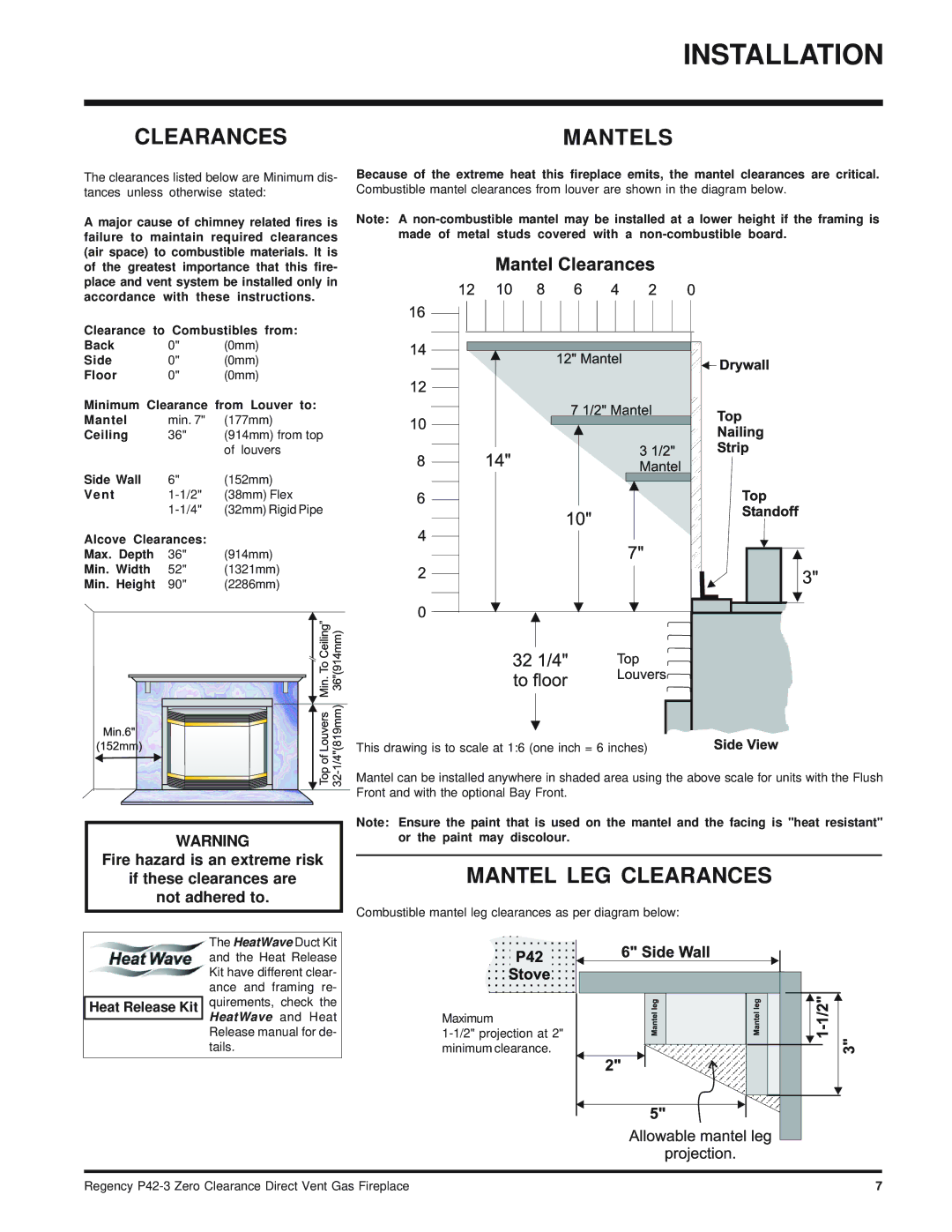
Because of the extreme heat this fireplace emits, the mantel clearances are critical. Combustible mantel clearances from louver are shown in the diagram below.
Note: A
This drawing is to scale at 1:6 (one inch = 6 inches)
![]()
![]()
![]()
![]() Mantel can be installed anywhere in shaded area using the above scale for units with the Flush
Mantel can be installed anywhere in shaded area using the above scale for units with the Flush ![]() Front and with the optional Bay Front.
Front and with the optional Bay Front.
WARNING
Fire hazard is an extreme risk
if these clearances are
not adhered to.
The HeatWave Duct Kit
and the Heat Release Kit have different clear- ance and framing re-
Heat Release Kit quirements, check the HeatWave and Heat
Release manual for de- tails.
Note: Ensure the paint that is used on the mantel and the facing is "heat resistant" or the paint may discolour.
MANTEL LEG CLEARANCES
Combustible mantel leg clearances as per diagram below:
Maximum
Regency | 7 |