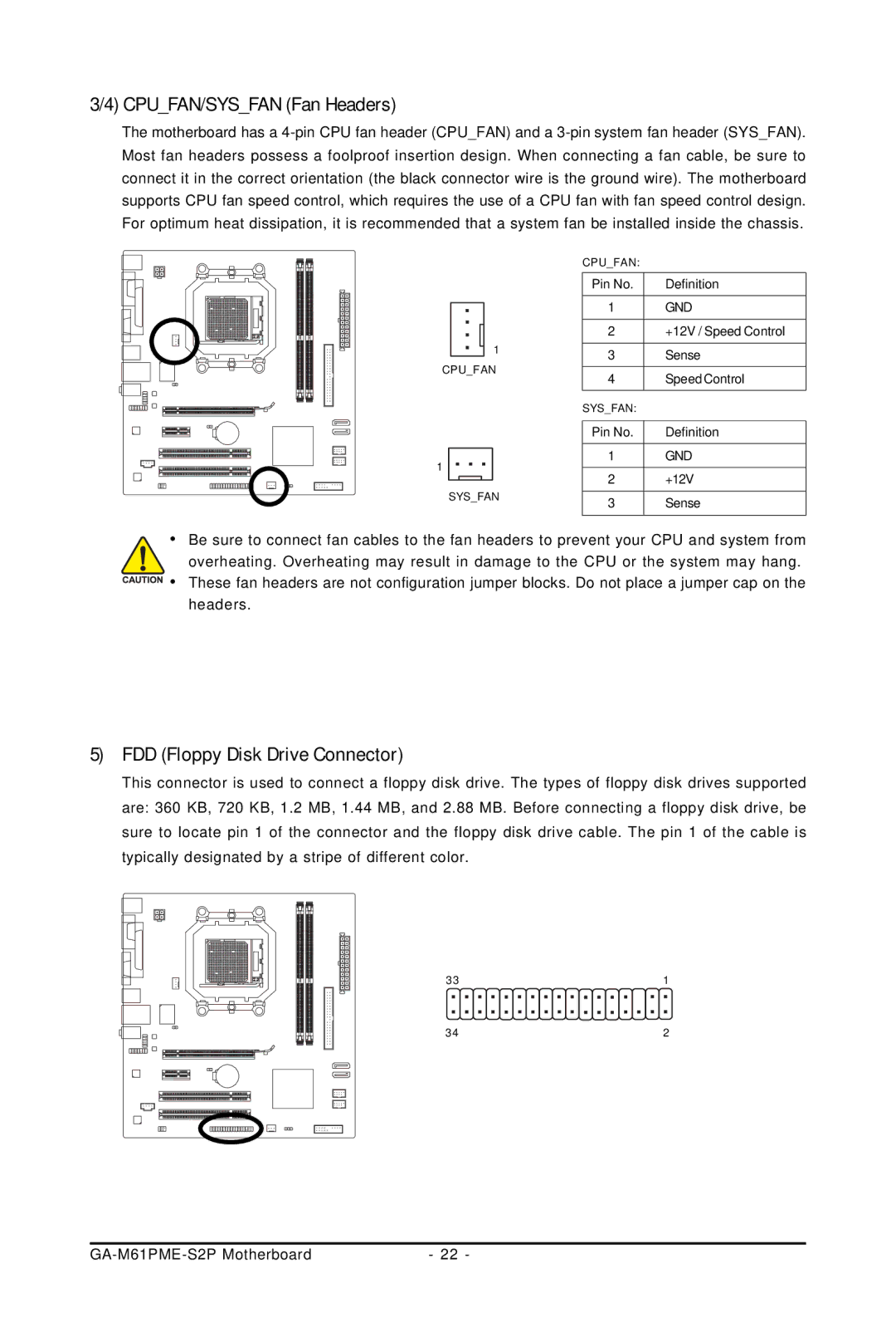
3/4) CPU_FAN/SYS_FAN (Fan Headers)
The motherboard has a
|
|
|
|
| CPU_FAN: |
| |
|
|
|
|
| Pin No. | Definition | |
|
|
|
|
| 1 | GND | |
|
|
|
|
| |||
|
|
| 1 | 2 | +12V / Speed Control | ||
|
|
| |||||
|
|
| 3 | Sense | |||
CPU_FAN |
|
| |||||
4 | Speed Control | ||||||
|
|
|
|
| |||
|
|
|
|
| SYS_FAN: |
| |
|
|
|
|
|
|
| |
|
|
|
|
| Pin No. | Definition | |
1 |
|
|
|
| 1 | GND | |
|
|
|
| ||||
|
|
|
| 2 | +12V | ||
|
|
|
|
| |||
| SYS_FAN | ||||||
| 3 | Sense | |||||
•Be sure to connect fan cables to the fan headers to prevent your CPU and system from
overheating. Overheating may result in damage to the CPU or the system may hang. ![]()
![]()
![]()
![]() • These fan headers are not configuration jumper blocks. Do not place a jumper cap on the
• These fan headers are not configuration jumper blocks. Do not place a jumper cap on the
headers.
5)FDD (Floppy Disk Drive Connector)
This connector is used to connect a floppy disk drive. The types of floppy disk drives supported are: 360 KB, 720 KB, 1.2 MB, 1.44 MB, and 2.88 MB. Before connecting a floppy disk drive, be sure to locate pin 1 of the connector and the floppy disk drive cable. The pin 1 of the cable is typically designated by a stripe of different color.
33 | 1 |
34 | 2 |
- 22 - |