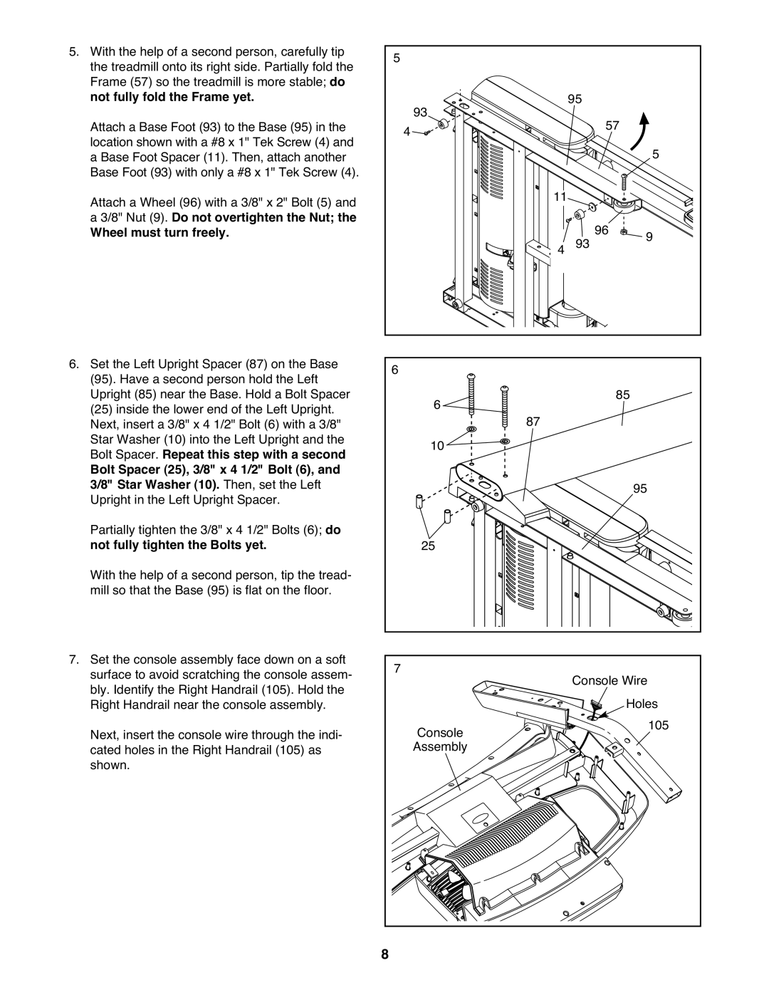
5.With the help of a second person, carefully tip the treadmill onto its right side. Partially fold the Frame (57) so the treadmill is more stable; do not fully fold the Frame yet.
Attach a Base Foot (93) to the Base (95) in the location shown with a #8 x 1" Tek Screw (4) and a Base Foot Spacer (11). Then, attach another Base Foot (93) with only a #8 x 1" Tek Screw (4). Attach a Wheel (96) with a 3/8" x 2" Bolt (5) and a 3/8" Nut (9). Do not overtighten the Nut; the
Wheel must turn freely.
6.Set the Left Upright Spacer (87) on the Base
(95).Have a second person hold the Left Upright (85) near the Base. Hold a Bolt Spacer
(25)inside the lower end of the Left Upright. Next, insert a 3/8" x 4 1/2" Bolt (6) with a 3/8" Star Washer (10) into the Left Upright and the Bolt Spacer. Repeat this step with a second
Bolt Spacer (25), 3/8" x 4 1/2" Bolt (6), and 3/8" Star Washer (10). Then, set the Left Upright in the Left Upright Spacer.
Partially tighten the 3/8" x 4 1/2" Bolts (6); do not fully tighten the Bolts yet.
With the help of a second person, tip the tread- mill so that the Base (95) is flat on the floor.
7.Set the console assembly face down on a soft surface to avoid scratching the console assem- bly. Identify the Right Handrail (105). Hold the Right Handrail near the console assembly. Next, insert the console wire through the indi- cated holes in the Right Handrail (105) as shown.
5 | 95 |
|
4 93 |
| |
57 | 5 | |
|
| |
11 | 93 96 | 9 |
4 |
6 | 85 |
6 | |
10 | 87 |
| |
| 95 |
25 |
|
7 | Console Wire |
Console | Holes |
105 | |
Assembly |
|
8