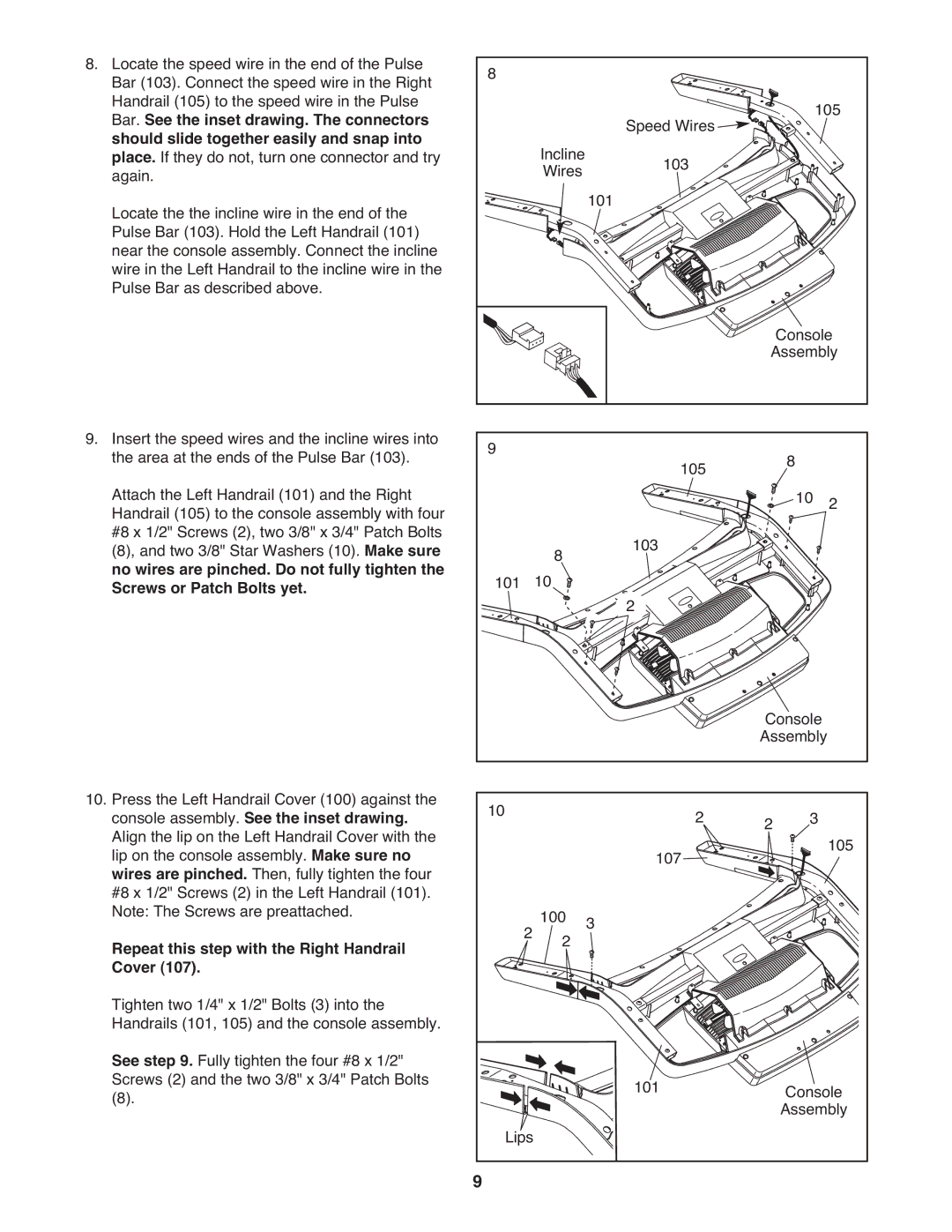
8. | Locate the speed wire in the end of the Pulse | 8 |
|
|
|
|
|
|
| Bar (103). Connect the speed wire in the Right |
|
|
|
|
|
| |
| Handrail (105) to the speed wire in the Pulse |
|
|
|
|
| 105 | |
| Bar. See the inset drawing. The connectors |
|
|
| Speed Wires |
| ||
| should slide together easily and snap into |
| Incline |
|
|
| ||
| place. If they do not, turn one connector and try |
| 103 |
|
|
| ||
| again. |
| Wires |
|
|
| ||
| Locate the the incline wire in the end of the |
|
|
| 101 |
|
|
|
| Pulse Bar (103). Hold the Left Handrail (101) |
|
|
|
|
|
|
|
| near the console assembly. Connect the incline |
|
|
|
|
|
|
|
| wire in the Left Handrail to the incline wire in the |
|
|
|
|
|
|
|
| Pulse Bar as described above. |
|
|
|
|
| Console | |
|
|
|
|
|
|
| ||
|
|
|
|
|
| Assembly | ||
9. | Insert the speed wires and the incline wires into | 9 |
|
| 105 |
| 8 |
|
| the area at the ends of the Pulse Bar (103). |
|
|
|
| |||
| Attach the Left Handrail (101) and the Right |
|
|
|
|
| 10 | 2 |
| Handrail (105) to the console assembly with four |
|
|
|
|
| ||
| #8 x 1/2" Screws (2), two 3/8" x 3/4" Patch Bolts |
|
|
| 103 |
|
|
|
| (8), and two 3/8" Star Washers (10). Make sure |
|
| 8 |
|
|
| |
| no wires are pinched. Do not fully tighten the | 101 | 10 |
|
|
|
| |
| Screws or Patch Bolts yet. |
| 2 |
|
|
| ||
|
|
|
|
|
|
|
| |
|
|
|
|
|
| Console |
| |
|
|
|
|
|
| Assembly |
| |
10. | Press the Left Handrail Cover (100) against the | 10 |
|
| 2 |
| 3 |
|
| console assembly. See the inset drawing. |
|
| 2 |
| |||
| Align the lip on the Left Handrail Cover with the |
|
|
|
|
| 105 | |
| lip on the console assembly. Make sure no |
|
|
| 107 |
|
| |
| wires are pinched. Then, fully tighten the four |
|
|
|
|
|
| |
| #8 x 1/2" Screws (2) in the Left Handrail (101). |
|
|
|
|
|
|
|
| Note: The Screws are preattached. |
| 2 1002 | 3 |
|
|
| |
| Repeat this step with the Right Handrail |
|
|
|
| |||
| Cover (107). |
|
|
|
|
|
|
|
| Tighten two 1/4" x 1/2" Bolts (3) into the |
|
|
|
|
|
|
|
| Handrails (101, 105) and the console assembly. |
|
|
|
|
|
|
|
| See step 9. Fully tighten the four #8 x 1/2" |
|
|
| 101 |
| Console | |
| Screws (2) and the two 3/8" x 3/4" Patch Bolts |
|
|
|
| |||
| (8). | Lips |
|
|
| Assembly | ||
|
|
|
|
|
|
| ||
|
| 9 |
|
|
|
|
|
|