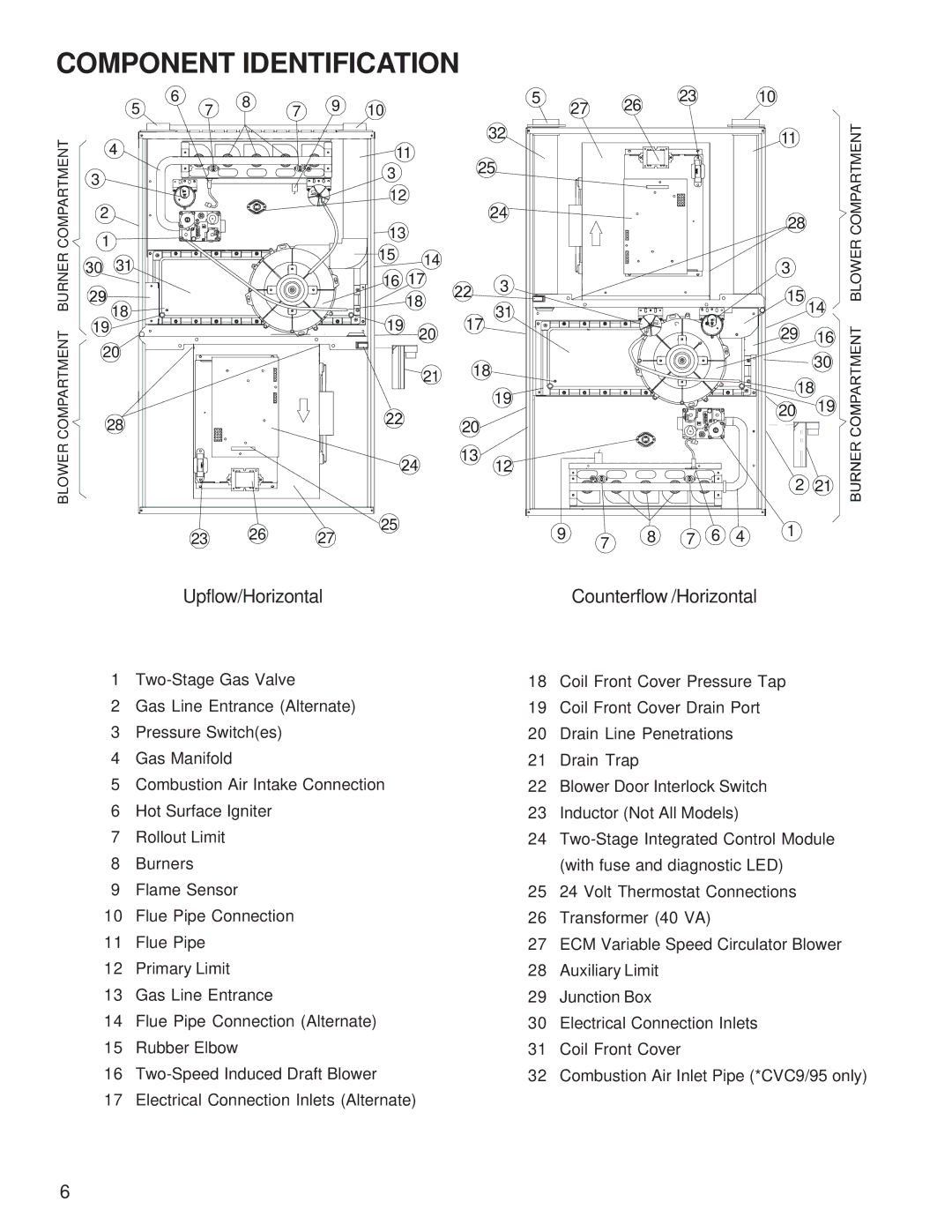
COMPONENT IDENTIFICATION


5

6

7

8

7

9

10


5

27

26

23


10


BLOWER COMPARTMENT

BURNER COMPARTMENT

4


11


32


11


25


3


3


12


2


24


*

*

*


28


*


13


*

*


1


*

*

*


15

14


31


3


16 17


3


15


18


18


31


14


19


19


17


COMPARTMENT


20


29

16


20


18


30


21


18


19


20

19


28


20


BLOWER


13

12


2

21


23

26

27

25


9

7

8

7

6

4

1


Upflow/Horizontal


Counterflow /Horizontal


1Two-Stage Gas Valve

2Gas Line Entrance (Alternate)

3Pressure Switch(es)

4Gas Manifold

5Combustion Air Intake Connection

6Hot Surface Igniter

7Rollout Limit

8Burners

9Flame Sensor

10Flue Pipe Connection

11Flue Pipe

12Primary Limit

13Gas Line Entrance

14Flue Pipe Connection (Alternate)

15Rubber Elbow

16Two-Speed Induced Draft Blower

17Electrical Connection Inlets (Alternate)

18Coil Front Cover Pressure Tap

19Coil Front Cover Drain Port

20Drain Line Penetrations

21Drain Trap

22Blower Door Interlock Switch

23Inductor (Not All Models)

24Two-Stage Integrated Control Module (with fuse and diagnostic LED)

2524 Volt Thermostat Connections

26Transformer (40 VA)

27ECM Variable Speed Circulator Blower

28Auxiliary Limit

29Junction Box

30Electrical Connection Inlets

31Coil Front Cover

32Combustion Air Inlet Pipe (*CVC9/95 only)

6

Page 6
Image 6
Goodman Mfg GCVC9/GMVC95, ACVC9/AMVC95, Goodman 90%-95% Gas Furnace Units service manual Component Identification

Goodman 90%-95% Gas Furnace Units, ACVC9/AMVC95, GCVC9/GMVC95 specifications

Goodman Manufacturing is a prominent name in the HVAC industry, known for providing energy-efficient solutions that cater to both residential and commercial environments. Among its offerings, the Goodman GCVC9/GMVC95 and ACVC9/AMVC95 models stand out as top-tier gas furnace units, with efficiency ratings between 90% and 95%. These furnaces provide an excellent balance of performance, reliability, and affordability.

The GCVC9 and GMVC95 gas furnace units are designed with advanced features that ensure optimal heating and comfort. One of the key characteristics of these models is their energy efficiency. With Annual Fuel Utilization Efficiency (AFUE) ratings of up to 95%, these furnaces convert nearly all the fuel they consume into heat, resulting in significant cost savings on energy bills. This makes them an ideal choice for homeowners looking to reduce their carbon footprint while maintaining a comfortable indoor environment.

These units are equipped with a two-stage gas valve and a variable-speed blower motor. The two-stage gas valve allows for precise temperature control by providing two levels of heating output, ensuring that the furnace runs at lower capacities during milder conditions and ramping up when more heat is needed. The variable-speed blower motor enhances comfort by providing consistent airflow, reducing temperature fluctuations, and operating more quietly than single-speed motors.

Another notable feature is the firing system, which utilizes a hot surface igniter for reliable operation. This technology enhances safety and performance, eliminating the need for a pilot light and minimizing gas waste. Additionally, both models are designed for easy installation and maintenance, with features like a compact design and convenient access to internal components.

Durability is also a hallmark of Goodman furnaces. The units are constructed with high-quality materials, including a heavy-gauge steel cabinet and a durable powder-coated finish to resist corrosion. Furthermore, Goodman offers exceptional warranties, including a lifetime heat exchanger warranty, providing peace of mind for homeowners.

In conclusion, the Goodman GCVC9/GMVC95 and ACVC9/AMVC95 gas furnace units are engineered for efficient heating with advanced technologies that enhance performance and comfort. Their high AFUE ratings, reliable ignition system, and durable construction make them excellent choices for anyone looking to invest in a reliable heating solution. With Goodman at the helm, homeowners can enjoy efficient heating without compromising on comfort or cost.