SERVICING
![]() WARNING
WARNING
To avoid possible explosion, the line from the nitrogen cylinder must include a pressure regulator and a pressure relief valve. The pressure relief valve must be set to open at no more than 150 psig.
Pressure test the system using dry nitrogen and soapy water to locate leaks. If you wish to use a leak detector, charge the system to 10 psi using the appropriate refrigerant then use nitrogen to finish charging the system to working pressure, then apply the detector to suspect areas. If leaks are found, repair them. After repair, repeat the pressure test. If no leaks exist, proceed to system evacuation.
S-102 EVACUATION
![]() WARNING
WARNING
REFRIGERANT UNDER PRESSURE!
Failure to follow proper procedures may cause property damage, personal injury or death.
This is the most important part of the entire service procedure. The life and efficiency of the equipment is dependent upon the thoroughness exercised by the serviceman when evacuating air
Air in a system causes high condensing temperature and pressure, resulting in increased power input and reduced performance.
Moisture chemically reacts with the refrigerant oil to form corrosive acids. These acids attack motor windings and parts, causing breakdown.
The equipment required to thoroughly evacuate the system is a high vacuum pump, capable of producing a vacuum equiva- lent to 25 microns absolute and a thermocouple vacuum gauge to give a true reading of the vacuum in the system
NOTE: Never use the system compressor as a vacuum pump or run when under a high vacuum. Motor damage could occur.
![]() WARNING
WARNING
Do not front seat the service valve(s) with the compressor open, with the suction line of the comprssor closed or severely restricted.
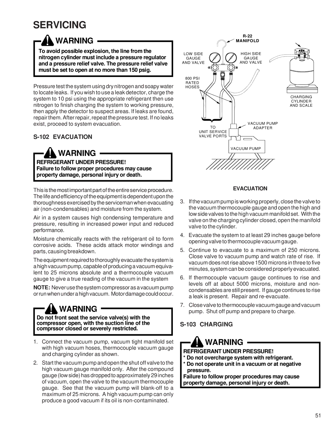
1.Connect the vacuum pump, vacuum tight manifold set with high vacuum hoses, thermocouple vacuum gauge and charging cylinder as shown.
2.Start the vacuum pump and open the shut off valve to the high vacuum gauge manifold only. After the compound gauge (low side) has dropped to approximately 29 inches of vacuum, open the valve to the vacuum thermocouple gauge. See that the vacuum pump will
| |
| MANIFOLD |
LOW SIDE | HIGH SIDE |
GAUGE | GAUGE |
AND VALVE | AND VALVE |
800 PSI RATED HOSES
CHARGING
CYLINDER
AND SCALE
{ |
| VACUUM PUMP |
| ||
TO |
| ADAPTER |
UNIT SERVICE |
|
|
VALVE PORTS |
|
|
| VACUUM PUMP | |
EVACUATION
3.If the vacuum pump is working properly, close the valve to the vacuum thermocouple gauge and open the high and low side valves to the high vacuum manifold set. With the valve on the charging cylinder closed, open the manifold valve to the cylinder.
4.Evacuate the system to at least 29 inches gauge before opening valve to thermocouple vacuum gauge.
5.Continue to evacuate to a maximum of 250 microns. Close valve to vacuum pump and watch rate of rise. If vacuum does not rise above 1500 microns in three to five minutes, system can be considered properly evacuated.
6.If thermocouple vacuum gauge continues to rise and levels off at about 5000 microns, moisture and non- condensables are still present. If gauge continues to rise a leak is present. Repair and
7.Close valve to thermocouple vacuum gauge and vacuum pump. Shut off pump and prepare to charge.
S-103 CHARGING
![]() WARNING
WARNING
REFRIGERANT UNDER PRESSURE!
*Do not overcharge system with refrigerant.
*Do not operate unit in a vacuum or at negative pressure.
Failure to follow proper procedures may cause property damage, personal injury or death.
51