ACCESSORIES WIRING DIAGRAMS
HIGH VOLTAGE!
DISCONNECT ALL POWER BEFORE SERVICING OR INSTALLING THIS
UNIT. MULTIPLE POWER SOURCES MAY BE PRESENT. FAILURE TO
DO SO MAY CAUSE PROPERTY DAMAGE, PERSONAL INJURY OR DEATH.
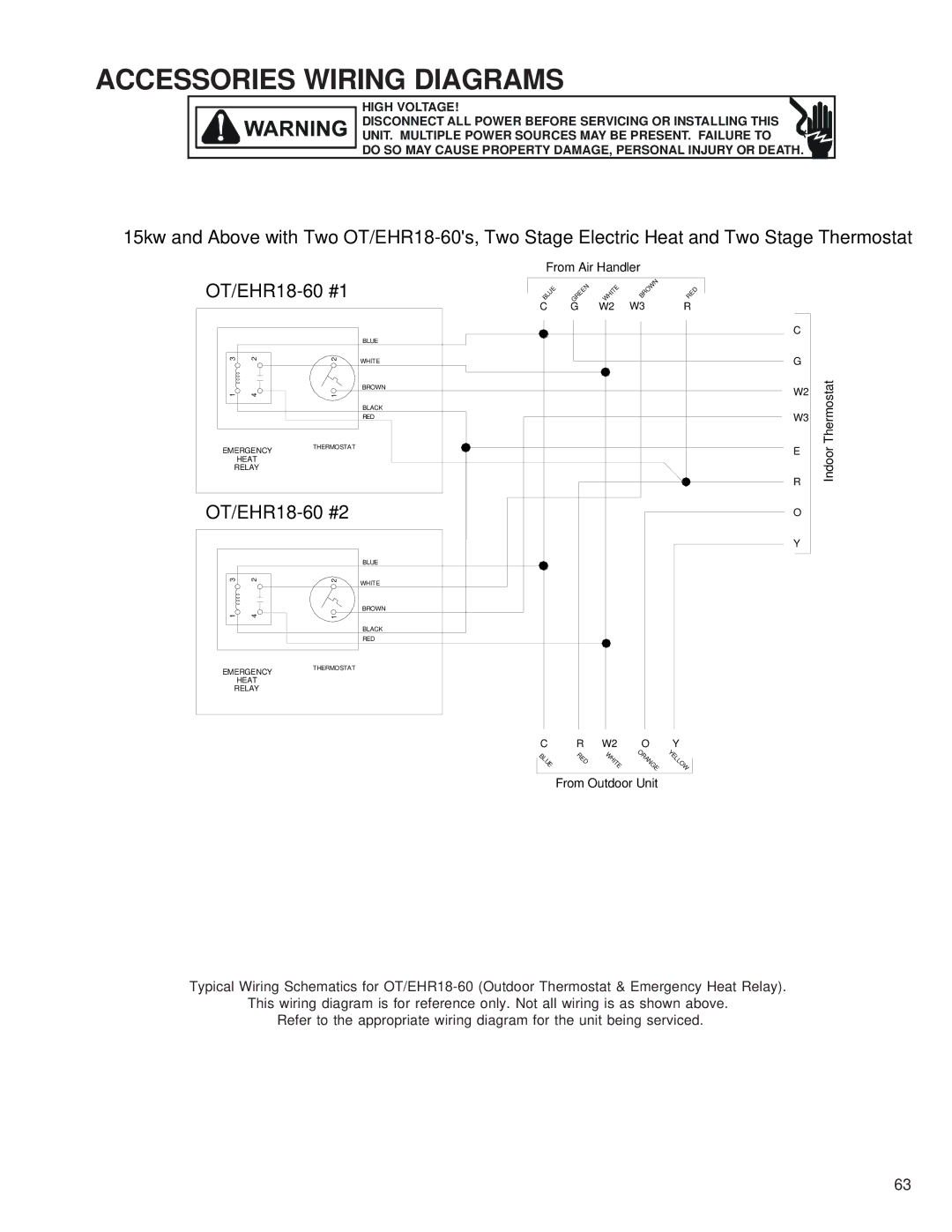
15kw and Above with Two
From Air Handler |
| ||||||
BLUE | GREEN | WHITE | BROWN | RE | |||
|
|
|
|
|
|
| D |
|
|
| C | G | W2 | W3 | R |
|
|
| BLUE |
|
|
| C |
|
|
|
|
|
|
| |
3 | 2 | 2 | WHITE |
|
|
| G |
|
|
|
|
|
| ||
1 | 4 |
| BROWN |
|
|
| W2 |
1 |
|
|
|
| |||
|
|
| BLACK |
|
|
| W3 |
|
|
| RED |
|
|
| |
EMERGENCY | THERMOSTAT |
|
|
|
| E | |
|
|
|
|
| |||
| HEAT |
|
|
|
|
|
|
RELAY |
|
|
|
|
|
| |
|
|
|
|
|
|
| R |
|
|
|
|
| O | ||
|
|
|
|
|
|
| Y |
|
|
| BLUE |
|
|
|
|
3 | 2 | 2 | WHITE |
|
|
|
|
|
|
|
|
|
|
| |
1 | 4 |
| BROWN |
|
|
|
|
1 |
|
|
|
|
| ||
|
|
| BLACK |
|
|
|
|
|
|
| RED |
|
|
|
|
EMERGENCY | THERMOSTAT |
|
|
|
|
| |
|
|
|
|
|
| ||
| HEAT |
|
|
|
|
|
|
RELAY |
|
|
|
|
|
| |
|
|
| C | R | W2 | O | Y |
|
|
| UE | R | WHITE | ORANGE | Y |
|
|
| LOW | ||||
|
|
| B |
|
| E | |
|
|
| L | E |
|
| L |
|
|
|
| D |
|
|
|
From Outdoor Unit
Indoor Thermostat
Typical Wiring Schematics for
This wiring diagram is for reference only. Not all wiring is as shown above. Refer to the appropriate wiring diagram for the unit being serviced.
63