SERVICING
B.Shorted - indicator swings to zero and stops there - replace.
C.Open - no reading - replace. (Start capacitor would read resistor resistance.)
S-15B CAPACITANCE CHECK
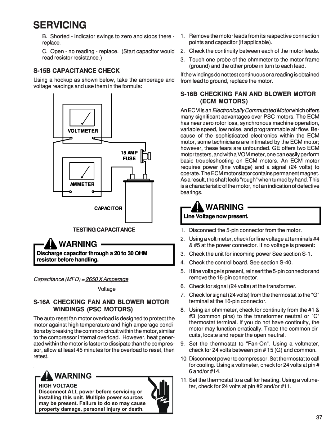
Using a hookup as shown below, take the amperage and voltage readings and use them in the formula:
VOLTMETER
15 AMP
FUSE
AMMETER
CAPACITOR
TESTING CAPACITANCE
![]() WARNING
WARNING
Discharge capacitor through a 20 to 30 OHM resistor before handling.
Capacitance (MFD) = 2650 X Amperage
Voltage
The auto reset fan motor overload is designed to protect the motor against high temperature and high amperage condi- tions by breaking the common circuit within the motor, similar to the compressor internal overload. However, heat gener- ated within the motor is faster to dissipate than the compres- sor, allow at least 45 minutes for the overload to reset, then retest.
1.Remove the motor leads from its respective connection points and capacitor (if applicable).
2.Check the continuity between each of the motor leads.
3.Touch one probe of the ohmmeter to the motor frame (ground) and the other probe in turn to each lead.
If the windings do not test continuous or a reading is obtained from lead to ground, replace the motor.
S-16B CHECKING FAN AND BLOWER MOTOR (ECM MOTORS)
An ECM is an Electronically Commutated Motor which offers many significant advantages over PSC motors. The ECM has near zero rotor loss, synchronous machine operation, variable speed, low noise, and programmable air flow. Be- cause of the sophisticated electronics within the ECM motor, some technicians are intimated by the ECM motor; however, these fears are unfounded. GE offers two ECM motor testers, and with a VOM meter, one can easily perform basic troubleshooting on ECM motors. An ECM motor requires power (line voltage) and a signal (24 volts) to operate. The ECM motor stator contains permanent magnet. As a result, the shaft feels "rough" when turned by hand. This is a characteristic of the motor, not an indication of defective bearings.
![]() WARNING
WARNING
Line Voltage now present.
1.Disconnect the
2.Using a volt meter, check for line voltage at terminals #4 & #5 at the power connector. If no voltage is present:
3.Check the unit for incoming power See section
4.Check the control board, See section
5.If line voltage is present, reinsert the
6.Check for signal (24 volts) at the transformer.
7.Check for signal (24 volts) from the thermostat to the "G" terminal at the
8.Using an ohmmeter, check for continuity from the #1 & #3 (common pins) to the transformer neutral or "C" thermostat terminal. If you do not have continuity, the motor may function erratically. Trace the common cir- cuits, locate and repair the open neutral.
9.Set the thermostat to
10.Disconnect power to compressor. Set thermostat to call for cooling. Using a voltmeter, check for 24 volts at pin # 6 and/or #14.
11.Set the thermostat to a call for heating. Using a voltme- ter, check for 24 volts at pin #2 and/or #11.
37