SERVICING
lation.
Other components such as a Heating/Cooling Thermostat and Outdoor Thermostats are available to complete the installation.
The system CFM can be determined by measuring the static pressure external to the unit. The installation manual supplied with the blower coil, or the blower performance table in the service manual, shows the CFM for the static mea- sured.
Alternately, the system CFM can be determined by operating the electric heaters and indoor blower WITHOUT having the compressor in operation. Measure the temperature rise as close to the blower inlet and outlet as possible.
If other than a 240V power supply is used, refer to the BTUH CAPACITY CORRECTION FACTOR chart below.
BTUH CAPACITY CORRECTION FACTOR
SUPPLY VOLTAGE | 250 230 220 208 |
MULTIPLICATION FACTOR 1.08 .92 .84 .75
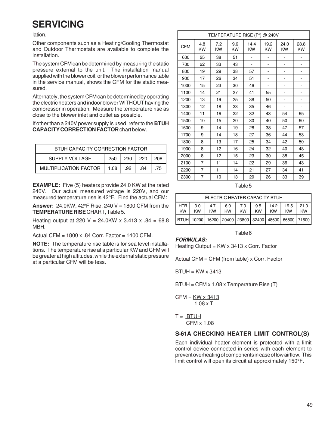
EXAMPLE: Five (5) heaters provide 24.0 KW at the rated 240V. Our actual measured voltage is 220V, and our measured temperature rise is 42°F. Find the actual CFM:
Answer: 24.0KW, 42°F Rise, 240 V = 1800 CFM from the TEMPERATURE RISE CHART, Table 5.
Heating output at 220 V = 24.0KW x 3.413 x .84 = 68.8 MBH.
Actual CFM = 1800 x .84 Corr. Factor = 1400 CFM.
NOTE: The temperature rise table is for sea level installa- tions. The temperature rise at a particular KW and CFM will be greater at high altitudes, while the external static pressure at a particular CFM will be less.
|
|
|
|
|
| TEMPERATURE RISE (F°) @ 240V |
|
|
|
|
| ||||||||||||||
|
|
|
|
|
|
|
|
|
|
|
|
|
|
|
|
|
|
|
|
|
|
|
| ||
| CFM |
| 4.8 |
| 7.2 |
| 9.6 |
| 14.4 |
| 19.2 |
| 24.0 |
| 28.8 |
| |||||||||
|
| KW |
| KW |
| KW |
| KW |
|
| KW |
|
| KW |
| KW |
| ||||||||
|
|
|
|
|
|
|
|
|
|
|
|
| |||||||||||||
|
|
|
|
|
|
|
|
|
|
|
|
|
|
|
|
|
|
|
|
|
|
|
|
|
|
| 600 |
|
| 25 |
|
| 38 |
| 51 |
|
| - |
|
| - |
| - |
| - |
| |||||
| 700 |
|
| 22 |
|
| 33 |
| 43 |
|
| - |
|
| - |
| - |
| - |
| |||||
| 800 |
|
| 19 |
|
| 29 |
| 38 |
|
| 57 |
|
| - |
| - |
| - |
| |||||
| 900 |
|
| 17 |
|
| 26 |
| 34 |
|
| 51 |
|
| - |
| - |
| - |
| |||||
| 1000 |
| 15 |
|
| 23 |
| 30 |
|
| 46 |
|
| - |
| - |
| - |
| ||||||
| 1100 |
| 14 |
|
| 21 |
| 27 |
|
| 41 |
|
| 55 |
| - |
| - |
| ||||||
| 1200 |
| 13 |
|
| 19 |
| 25 |
|
| 38 |
|
| 50 |
| - |
| - |
| ||||||
| 1300 |
| 12 |
|
| 18 |
| 23 |
|
| 35 |
|
| 46 |
| - |
| - |
| ||||||
| 1400 |
| 11 |
|
| 16 |
| 22 |
|
| 32 |
|
| 43 |
| 54 |
| 65 |
| ||||||
| 1500 |
| 10 |
|
| 15 |
| 20 |
|
| 30 |
|
| 40 |
| 50 |
| 60 |
| ||||||
| 1600 |
| 9 |
|
| 14 |
| 19 |
|
| 28 |
|
| 38 |
| 47 |
| 57 |
| ||||||
| 1700 |
| 9 |
|
| 14 |
| 18 |
|
| 27 |
|
| 36 |
| 44 |
| 53 |
| ||||||
| 1800 |
| 8 |
|
| 13 |
| 17 |
|
| 25 |
|
| 34 |
| 42 |
| 50 |
| ||||||
| 1900 |
| 8 |
|
| 12 |
| 16 |
|
| 24 |
|
| 32 |
| 40 |
| 48 |
| ||||||
| 2000 |
| 8 |
|
| 12 |
| 15 |
|
| 23 |
|
| 30 |
| 38 |
| 45 |
| ||||||
| 2100 |
| 7 |
|
| 11 |
| 14 |
|
| 22 |
|
| 29 |
| 36 |
| 43 |
| ||||||
| 2200 |
| 7 |
|
| 11 |
| 14 |
|
| 21 |
|
| 27 |
| 34 |
| 41 |
| ||||||
| 2300 |
| 7 |
|
| 10 |
| 13 |
|
| 20 |
|
| 26 |
| 33 |
| 39 |
| ||||||
|
|
|
|
|
|
|
|
|
|
| Table 5 |
|
|
|
|
|
|
|
|
| |||||
|
|
|
|
|
|
|
| ||||||||||||||||||
|
|
|
|
| ELECTRIC HEATER CAPACITY BTUH |
|
| ||||||||||||||||||
|
|
|
|
|
|
|
|
|
|
|
|
|
|
|
|
|
|
|
| ||||||
| HTR |
| 3.0 |
| 4.7 |
| 6.0 | 7.0 |
|
| 9.5 |
|
| 14.2 |
| 19.5 |
| 21.0 |
| ||||||
| KW |
|
| KW |
| KW |
| KW | KW |
|
| KW |
|
| KW |
| KW | KW |
| ||||||
BTUH |
| 10200 |
| 16200 |
| 20400 | 23800 |
| 32400 |
| 48600 |
| 66500 | 71600 |
| ||||||||||
|
|
|
|
|
|
|
|
|
|
|
|
|
|
|
|
|
|
|
|
|
|
|
|
|
|
Table 6
FORMULAS:
Heating Output = KW x 3413 x Corr. Factor
Actual CFM = CFM (from table) x Corr. Factor
BTUH = KW x 3413
BTUH = CFM x 1.08 x Temperature Rise (T)
CFM = KW x 3413 1.08 x T
T = BTUH
CFM x 1.08
S-61A CHECKING HEATER LIMIT CONTROL(S)
Each individual heater element is protected with a limit control device connected in series with each element to prevent overheating of components in case of low airflow. This limit control will open its circuit at approximately 150°F.
49