SERVICING
S-105B THERMOSTATIC EXPANSION VALVE
The expansion valve is designed to control the rate of liquid refrigerant flow into an evaporator coil in exact proportion to
Remote | Orifice |
Condenser | Size |
A/GSX130181A | 0.049 |
A/GSX130181B | 0.051 |
A/GSX130241A | 0.053 |
A/GSX130241B | 0.057 |
A/GSX130301 | 0.059 |
A/GSX130301B | 0.061 |
A/GSX130361A | 0.068 |
A/GSX130361B | 0.070 |
A/GSX130421A | 0.074 |
A/GSX130421B | 0.076 |
A/GSX130481A | 0.080 |
A/GSX130481B | 0.080 |
A/GSX130601 | 0.092 |
SSX140181A | 0.049 |
SSX140241A | 0.057 |
SSX140301A | 0.063 |
SSX140361A | 0.067 |
SSX140421A | 0.074 |
SSX140421B | 0.074 |
SSX140481A | 0.079 |
SSX140601A | 0.088 |
A/SSX140181B | 0.052 |
A/SSX140241B | 0.055 |
A/SSX140301B | 0.065 |
A/SSX140361B | 0.070 |
Remote | Orifice |
Heat Pump | Size |
A/GSZ130181 | 0.049 |
A/GSZ130241 | 0.057 |
A/GSZ130301 | 0.063 |
A/GSZ130361 | 0.068 |
A/GSZ130421 | 0.074 |
A/GSZ130481 | 0.078 |
A/GSZ130601 | 0.088 |
SSZ140361A* | 0.071 |
SSZ140421A* | 0.076 |
SSZ140481A* | 0.080 |
SSZ140601A* | 0.088 |
the rate of evaporation of the refrigerant in the coil. The amount of refrigerant entering the coil is regulated since the valve responds to temperature of the refrigerant gas leaving the coil (feeler bulb contact) and the pressure of the refrigerant in the coil. This regulation of the flow prevents the return of liquid refrigerant to the compressor.
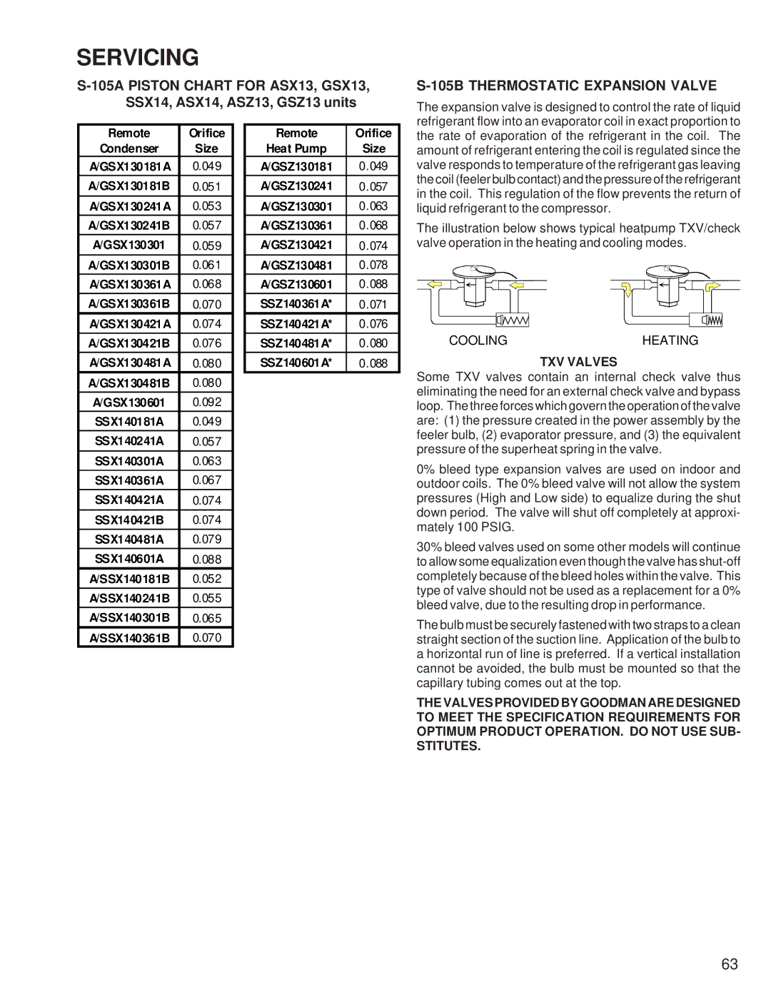
The illustration below shows typical heatpump TXV/check valve operation in the heating and cooling modes.
COOLINGHEATING
TXV VALVES
Some TXV valves contain an internal check valve thus eliminating the need for an external check valve and bypass loop. The three forces which govern the operation of the valve are: (1) the pressure created in the power assembly by the feeler bulb, (2) evaporator pressure, and (3) the equivalent pressure of the superheat spring in the valve.
0% bleed type expansion valves are used on indoor and outdoor coils. The 0% bleed valve will not allow the system pressures (High and Low side) to equalize during the shut down period. The valve will shut off completely at approxi- mately 100 PSIG.
30% bleed valves used on some other models will continue to allow some equalization even though the valve has
The bulb must be securely fastened with two straps to a clean straight section of the suction line. Application of the bulb to a horizontal run of line is preferred. If a vertical installation cannot be avoided, the bulb must be mounted so that the capillary tubing comes out at the top.
THE VALVES PROVIDED BY GOODMAN ARE DESIGNED TO MEET THE SPECIFICATION REQUIREMENTS FOR OPTIMUM PRODUCT OPERATION. DO NOT USE SUB- STITUTES.
63