SERVICING
S-4 CHECKING TRANSFORMER
AND CONTROL CIRCUIT
HIGH VOLTAGE!
Disconnect ALL power before servicing or installing. Multiple power sources may be present. Failure to do so may cause property damage, personal injury or death.
A
![]() WARNING
WARNING
Disconnect ALL power before servicing.
1.Remove control panel cover, or etc., to gain access to transformer.
With power ON:
![]() WARNING
WARNING
Line Voltage now present.
2.Using a voltmeter, check voltage across secondary volt- age side of transformer (R to C).
3.No voltage indicates faulty transformer, bad wiring, or bad splices.
4.Check transformer primary voltage at incoming line volt- age connections and/or splices.
5If line voltage available at primary voltage side of trans- former and wiring and splices good, transformer is inop- erative. Replace.
S-5 CHECKING CYCLE PROTECTOR
Some models feature a solid state,
The component is normally closed (R1 to Y1). A power interruption will break circuit (R1 to Y1) for approximately three minutes before resetting.
1.Remove wire from Y1 terminal.
2.Wait for approximately four (4) minutes if machine was running.
With power ON:
![]() WARNING
WARNING
Line Voltage now present.
1.Apply 24 VAC to terminals R1 and R2.
2.Should read 24 VAC at terminals Y1 and Y2.
3.Remove 24 VAC at terminals R1 and R2.
4.Should read 0 VAC at Y1 and Y2.
5.Reapply 24 VAC to R1 and R2 - within approximately three (3) to four (4) minutes should read 24 VAC at Y1 and Y2.
If not as above - replace relay.
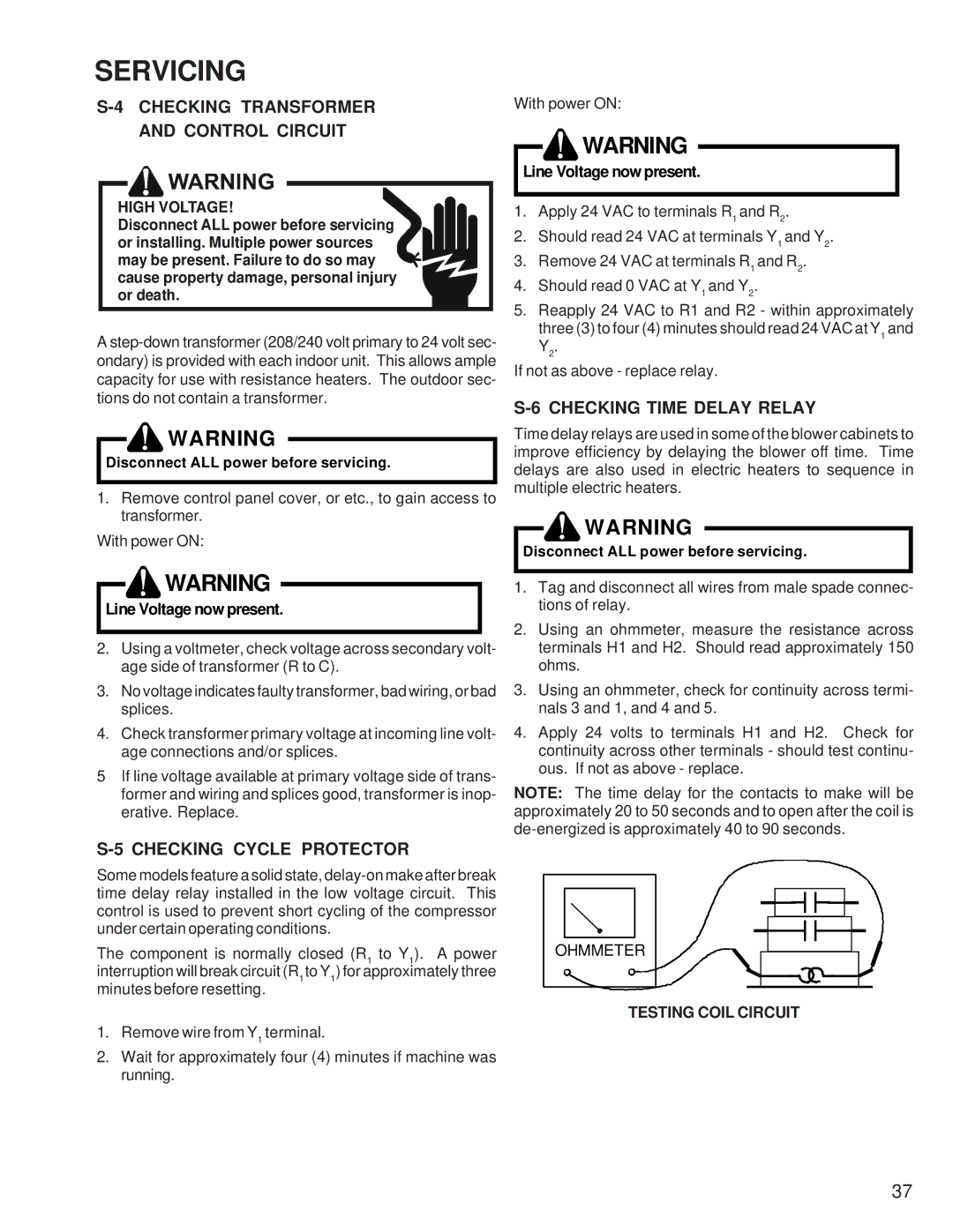
S-6 CHECKING TIME DELAY RELAY
Time delay relays are used in some of the blower cabinets to improve efficiency by delaying the blower off time. Time delays are also used in electric heaters to sequence in multiple electric heaters.
![]() WARNING
WARNING
Disconnect ALL power before servicing.
1.Tag and disconnect all wires from male spade connec- tions of relay.
2.Using an ohmmeter, measure the resistance across terminals H1 and H2. Should read approximately 150 ohms.
3.Using an ohmmeter, check for continuity across termi- nals 3 and 1, and 4 and 5.
4.Apply 24 volts to terminals H1 and H2. Check for continuity across other terminals - should test continu- ous. If not as above - replace.
NOTE: The time delay for the contacts to make will be approximately 20 to 50 seconds and to open after the coil is
OHMMETER
TESTING COIL CIRCUIT
37