SERVICING
4.
NOTE: When the outdoor unit is located above the indoor coil, the maximum vertical rise must not exceed 25 feet. If the maximum vertical rise exceeds 25 feet, premature compressor failure will occur due to inad- equate oil return.
5.Most refrigerant tubing kits are supplied with 3/8"- thick insulation on the vapor line. For long line installations over 80 feet that pass through a high ambient temperature,
6.Vibration and Noise: In long line applications, refriger- ant tubing is highly prone to transmit noise and vibration to the structure it is fastened to. Use adequate vibration- isolating hardware when mounting line set to adjacent structure.
Table 4 lists multiplier values to recalculate
TABLE 4. CAPACITY MULTIPLIERS AS A FUNCTION OF SUCTION LINE SIZE & EQUIVALENT LENGTH
Nominal | Vapor line |
| EQUIVALENT LINE LENGTH (FT) |
| |||
capacity | diameter |
|
|
|
|
|
|
|
|
|
|
|
| ||
Btuh | (in.) | 50 | 75 | 100 | 125 |
| 150 |
18,000 | 3/4 | .99 | .97 | .96 | .95 |
| .95 |
24,000 | 3/4 | 1 | .99 | .99 | .98 |
| .97 |
30,000 | 3/4 | .98 | .97 | .96 | .95 |
| .94 |
36,000 | 3/4 | .93 | .90 | .86 | .83 |
| .79 |
7/8 | .98 | .96 | .94 | .92 |
| .90 | |
|
| ||||||
42,000 | 3/4 | .93 | .90 | .87 | .83 |
| .80 |
7/8 | .97 | .96 | .94 | .93 |
| .92 | |
| 1 | 1 | .99 | .99 |
| .98 | |
48,000 | 3/4 | .90 | .86 | .82 | .78 |
| N/R |
7/8 | .96 | .94 | .93 | .91 |
| .89 | |
| 1 | 1 | .99 | .99 |
| .98 | |
60,000 | 7/8 | .93 | .91 | .89 | .86 |
| .84 |
.99 | .98 | .98 | .97 |
| .97 | ||
|
| ||||||
NOTE: For a condenser with a liquid valve tube connection less than 3/8" diameter, use 3/8" liquid line tubing for a line set greater than 25 feet.
TABLE 5. LOSSES FROM SUCTION LINE ELBOWS
(EQUIVALENT LENGTH, FT.)
Type of elbow fitting |
| I.D. (in.) |
| |
3/4 | 7/8 | |||
| ||||
90° short radius | 1.7 | 2 | 2.3 | |
90° long radius | 1.5 | 1.7 | 1.6 | |
45° | 0.7 | 0.8 | 1 |
Installation Requirements
1.In a completely horizontal installation with a long line set where the evaporator is at the same altitude as (or slightly below) the condenser, the line set should be sloped towards the evaporator. This helps reduce refrigerant migration to the condenser during a system’s
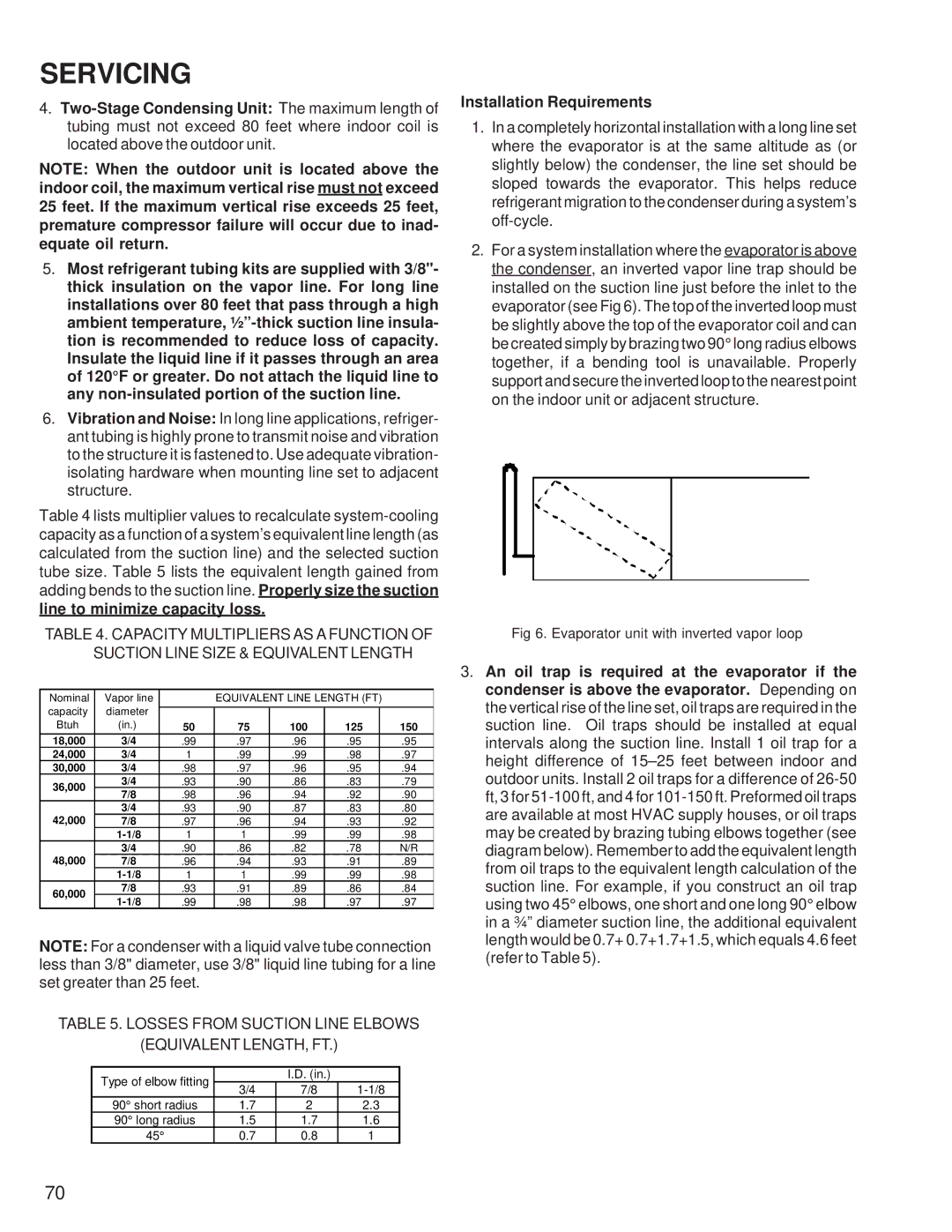
2.For a system installation where the evaporator is above the condenser, an inverted vapor line trap should be installed on the suction line just before the inlet to the evaporator (see Fig 6). The top of the inverted loop must be slightly above the top of the evaporator coil and can be created simply by brazing two 90° long radius elbows together, if a bending tool is unavailable. Properly support and secure the inverted loop to the nearest point on the indoor unit or adjacent structure.
Fig 6. Evaporator unit with inverted vapor loop
3.An oil trap is required at the evaporator if the condenser is above the evaporator. Depending on the vertical rise of the line set, oil traps are required in the suction line. Oil traps should be installed at equal intervals along the suction line. Install 1 oil trap for a height difference of
70