SERVICING
Mounting the condensing unit above the evaporator coil will require oil traps at equal intervals along the suction line. Install 1 oil trap for a height difference of
Install 2 oil traps for a difference of
Fig 7. Oil Trap Placement
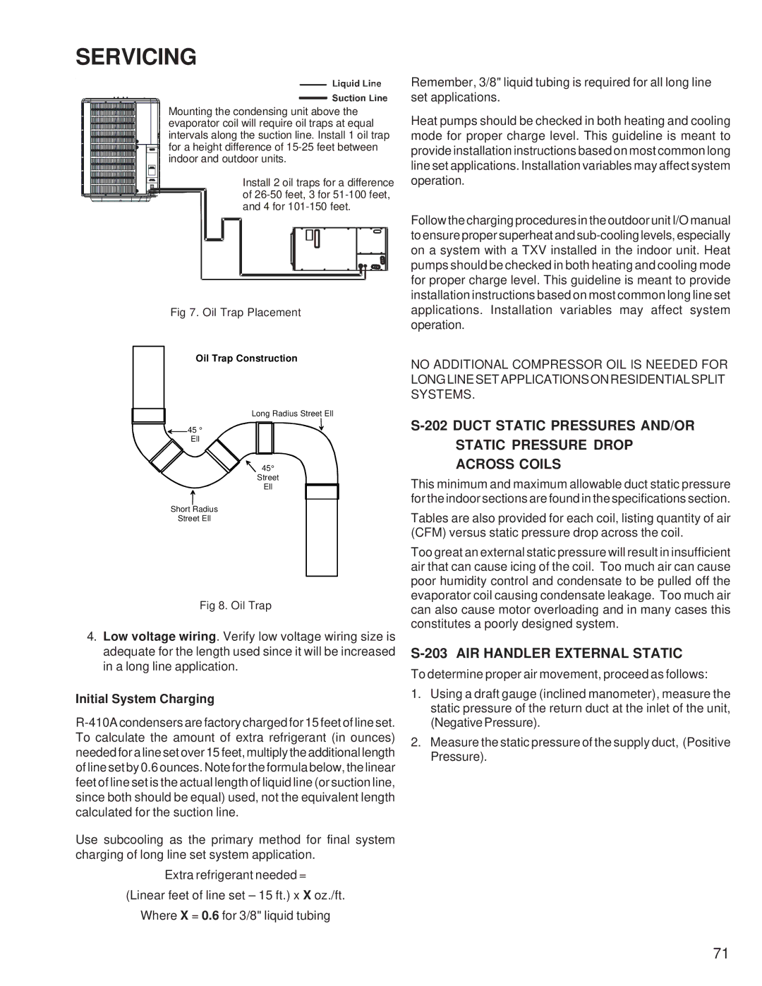
Oil Trap Construction
Long Radius Street Ell
![]() 45 °
45 °
Ell
45°
Street
Ell
Short Radius
Street Ell
Fig 8. Oil Trap
4.Low voltage wiring. Verify low voltage wiring size is adequate for the length used since it will be increased in a long line application.
Initial System Charging
Use subcooling as the primary method for final system charging of long line set system application.
Extra refrigerant needed =
(Linear feet of line set – 15 ft.) x X oz./ft.
Where X = 0.6 for 3/8" liquid tubing
Remember, 3/8" liquid tubing is required for all long line set applications.
Heat pumps should be checked in both heating and cooling mode for proper charge level. This guideline is meant to provide installation instructions based on most common long line set applications. Installation variables may affect system operation.
Follow the charging procedures in the outdoor unit I/O manual to ensure proper superheat and
NO ADDITIONAL COMPRESSOR OIL IS NEEDED FOR LONGLINESETAPPLICATIONSONRESIDENTIALSPLIT SYSTEMS.
This minimum and maximum allowable duct static pressure for the indoor sections are found in the specifications section.
Tables are also provided for each coil, listing quantity of air (CFM) versus static pressure drop across the coil.
Too great an external static pressure will result in insufficient air that can cause icing of the coil. Too much air can cause poor humidity control and condensate to be pulled off the evaporator coil causing condensate leakage. Too much air can also cause motor overloading and in many cases this constitutes a poorly designed system.
S-203 AIR HANDLER EXTERNAL STATIC
To determine proper air movement, proceed as follows:
1.Using a draft gauge (inclined manometer), measure the static pressure of the return duct at the inlet of the unit, (Negative Pressure).
2.Measure the static pressure of the supply duct, (Positive Pressure).
71