Installation
Pneumatic Agitator Motor
Always maintain a minimum of one inch clearance between rotating agitator parts and container to pre- vent sparks caused by contact.
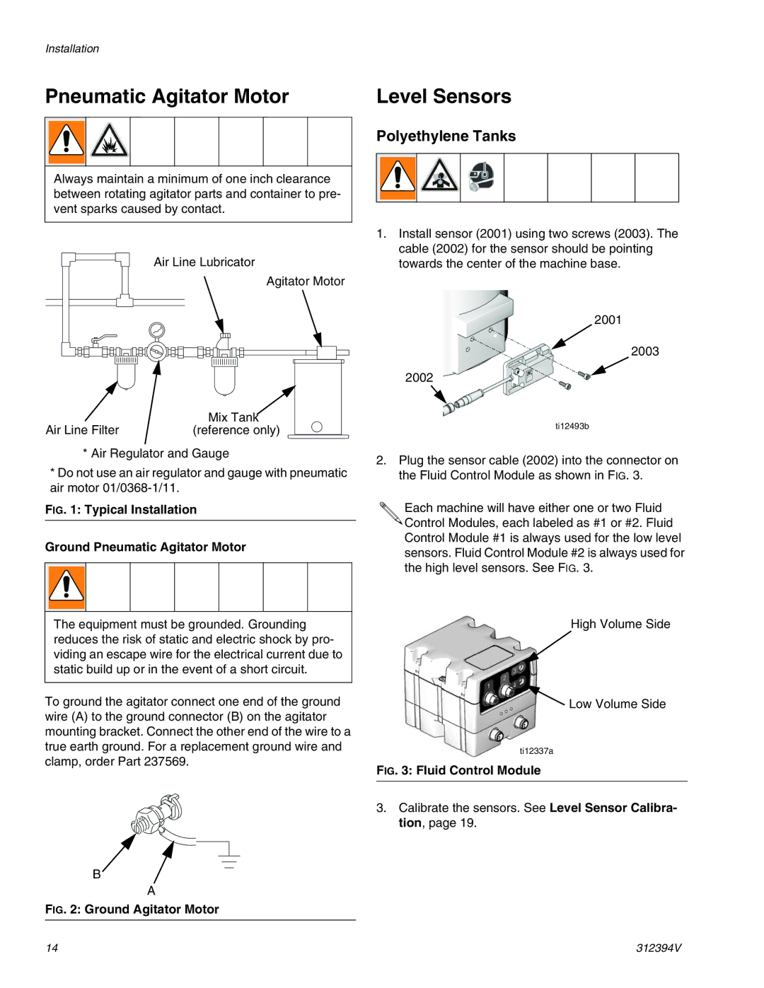
Air Line Lubricator
Agitator Motor
| Mix Tank |
Air Line Filter | (reference only) |
*Air Regulator and Gauge
*Do not use an air regulator and gauge with pneumatic air motor
FIG. 1: Typical Installation
Ground Pneumatic Agitator Motor
The equipment must be grounded. Grounding reduces the risk of static and electric shock by pro- viding an escape wire for the electrical current due to static build up or in the event of a short circuit.
To ground the agitator connect one end of the ground wire (A) to the ground connector (B) on the agitator mounting bracket. Connect the other end of the wire to a true earth ground. For a replacement ground wire and clamp, order Part 237569.
B![]()
A
FIG. 2: Ground Agitator Motor
Level Sensors
Polyethylene Tanks
1.Install sensor (2001) using two screws (2003). The cable (2002) for the sensor should be pointing towards the center of the machine base.
2001
2003
2002
ti12493b
2.Plug the sensor cable (2002) into the connector on the Fluid Control Module as shown in FIG. 3.
Each machine will have either one or two Fluid ![]()
![]() Control Modules, each labeled as #1 or #2. Fluid Control Module #1 is always used for the low level sensors. Fluid Control Module #2 is always used for the high level sensors. See FIG. 3.
Control Modules, each labeled as #1 or #2. Fluid Control Module #1 is always used for the low level sensors. Fluid Control Module #2 is always used for the high level sensors. See FIG. 3.
High Volume Side
![]() Low Volume Side
Low Volume Side
ti12337a
FIG. 3: Fluid Control Module
3.Calibrate the sensors. See Level Sensor Calibra- tion, page 19.
14 | 312394V |