Stainless Steel Tanks
2102
2101
2103
ti12494a
2104
Installation
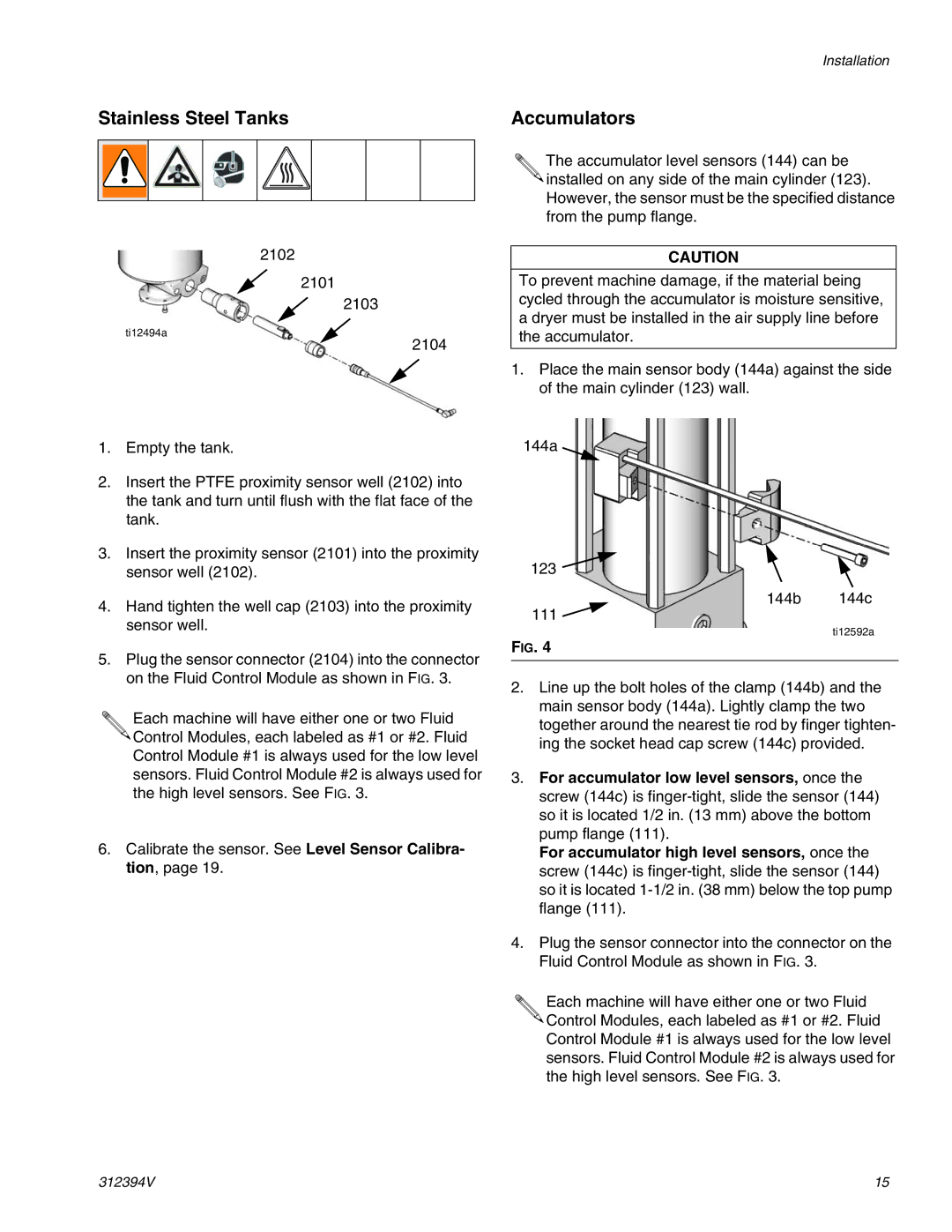
Accumulators
The accumulator level sensors (144) can be ![]()
![]() installed on any side of the main cylinder (123). However, the sensor must be the specified distance from the pump flange.
installed on any side of the main cylinder (123). However, the sensor must be the specified distance from the pump flange.
CAUTION
To prevent machine damage, if the material being cycled through the accumulator is moisture sensitive, a dryer must be installed in the air supply line before the accumulator.
1.Place the main sensor body (144a) against the side of the main cylinder (123) wall.
1.Empty the tank.
2.Insert the PTFE proximity sensor well (2102) into the tank and turn until flush with the flat face of the tank.
3.Insert the proximity sensor (2101) into the proximity sensor well (2102).
4.Hand tighten the well cap (2103) into the proximity sensor well.
5.Plug the sensor connector (2104) into the connector on the Fluid Control Module as shown in FIG. 3.
Each machine will have either one or two Fluid ![]()
![]() Control Modules, each labeled as #1 or #2. Fluid Control Module #1 is always used for the low level sensors. Fluid Control Module #2 is always used for the high level sensors. See FIG. 3.
Control Modules, each labeled as #1 or #2. Fluid Control Module #1 is always used for the low level sensors. Fluid Control Module #2 is always used for the high level sensors. See FIG. 3.
6.Calibrate the sensor. See Level Sensor Calibra- tion, page 19.
144a
123
144b 144c
111 ![]()
ti12592a
FIG. 4
2.Line up the bolt holes of the clamp (144b) and the main sensor body (144a). Lightly clamp the two together around the nearest tie rod by finger tighten- ing the socket head cap screw (144c) provided.
3.For accumulator low level sensors, once the screw (144c) is
For accumulator high level sensors, once the screw (144c) is
4.Plug the sensor connector into the connector on the Fluid Control Module as shown in FIG. 3.
Each machine will have either one or two Fluid ![]()
![]() Control Modules, each labeled as #1 or #2. Fluid Control Module #1 is always used for the low level sensors. Fluid Control Module #2 is always used for the high level sensors. See FIG. 3.
Control Modules, each labeled as #1 or #2. Fluid Control Module #1 is always used for the low level sensors. Fluid Control Module #2 is always used for the high level sensors. See FIG. 3.
312394V | 15 |