Setup
Setup
1.Engage trigger lock.
2.Install cutter:
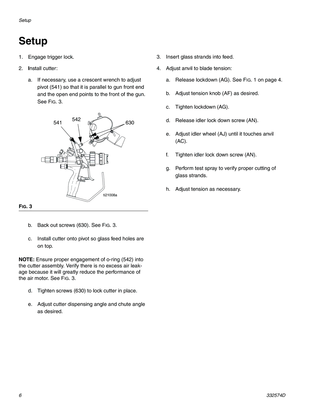
a.If necessary, use a crescent wrench to adjust pivot (541) so that it is parallel to gun front end and the open end points to the front of the gun. See FIG. 3.
541 | 542 | 630 |
|
ti21008a
FIG. 3
b.Back out screws (630). See FIG. 3.
c.Install cutter onto pivot so glass feed holes are on top.
NOTE: Ensure proper engagement of
d.Tighten screws (630) to lock cutter in place.
e.Adjust cutter dispensing angle and chute angle as desired.
3.Insert glass strands into feed.
4.Adjust anvil to blade tension:
a.Release lockdown (AG). See FIG. 1 on page 4.
b.Adjust tension knob (AF) as desired.
c.Tighten lockdown (AG).
d.Release idler lock down screw (AN).
e.Adjust idler wheel (AJ) until it touches anvil (AC).
f.Tighten idler lock down screw (AN).
g.Perform test spray to verify proper cutting of glass strands.
h.Adjust tension as necessary.
6 | 332574D |
