Displacement Pump Replacement
Displacement Pump Replacement
See manual 309250 for pump repair instructions.
4.Cycle pump until pin (32) is in position to be removed.
Removal
WARNING
Read Injection Hazard Warning, page 3, Moving Parts Hazard Warning, page 4 and Pressure Relief Procedure, page 8.
1.Relieve pressure, page 8.
2.Loosen two screws (30) and rotate cover (44).
ti6104a
44
30
3.Loosen nut (A) and remove hose set (35). Loosen nut (B) and remove the high pressure hose (14).
14
B
A
ti6105a
35
5.Disconnect power cord from outlet.
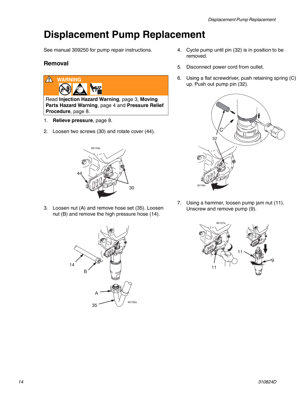
6.Using a flat screwdriver, push retaining spring (C) up. Push out pump pin (32).
C
32
ti6106a
7.Using a hammer, loosen pump jam nut (11). Unscrew and remove pump (9).
ti6107a
11
![]() 9
9
11
14 | 310824D |