Wiring Diagram
Wiring Diagram
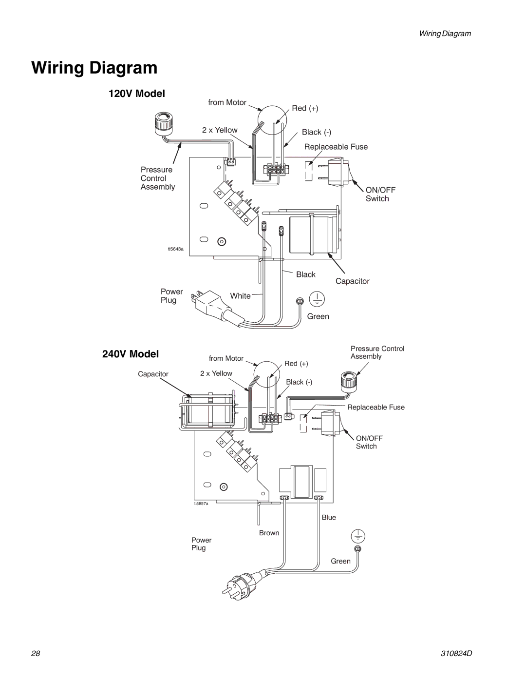
120V Model
from Motor
2 x Yellow
Pressure
Control
Assembly
ti5643a
Power
PlugWhite
240V Model | from Motor |
| |
Capacitor | 2 x Yellow |
Red (+)
Black
Replaceable Fuse
ON/OFF
Switch
Black
Capacitor
Green
Pressure Control
Assembly
Red (+)
Black
Replaceable Fuse
ON/OFF
Switch
ti5857a
Brown
Power
Plug
Blue
Green
28 | 310824D |