Spin Test
See Wiring Diagram, page 28.
WARNING
Read Electric Shock Warning, page 3 and Pressure Relief Procedure, page 8.
To check armature, motor winding and brush electrical continuity:
1.Relieve pressure, page 8. Disconnect power cord from outlet.
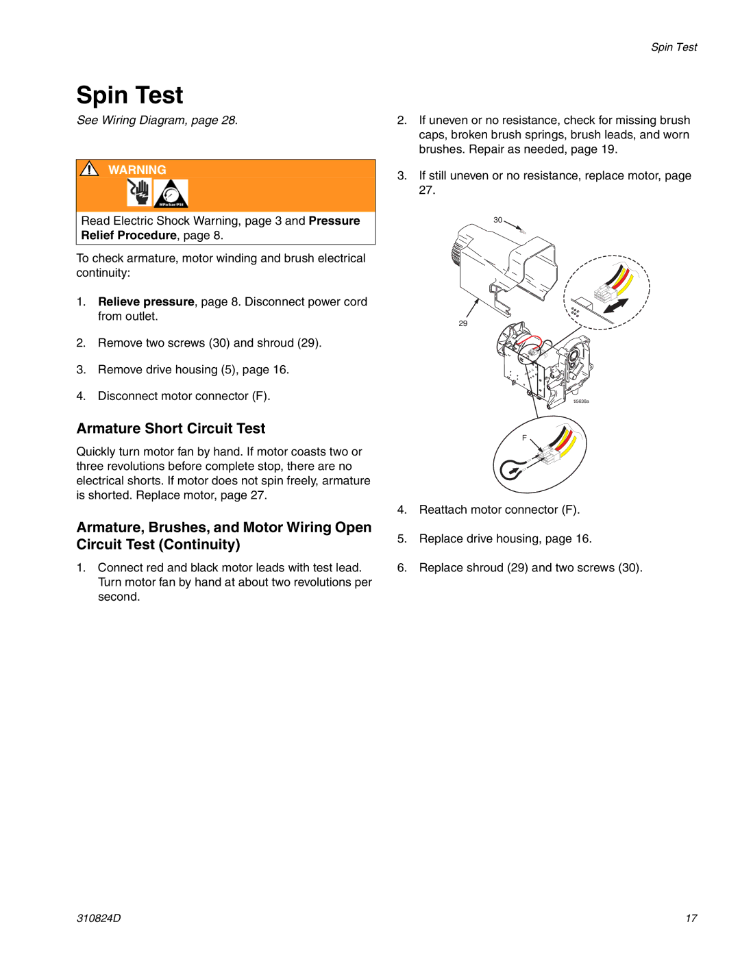
2.Remove two screws (30) and shroud (29).
3.Remove drive housing (5), page 16.
4.Disconnect motor connector (F).
Spin Test
2.If uneven or no resistance, check for missing brush caps, broken brush springs, brush leads, and worn brushes. Repair as needed, page 19.
3.If still uneven or no resistance, replace motor, page 27.
30
29
ti5638a
Armature Short Circuit Test
Quickly turn motor fan by hand. If motor coasts two or three revolutions before complete stop, there are no electrical shorts. If motor does not spin freely, armature is shorted. Replace motor, page 27.
Armature, Brushes, and Motor Wiring Open Circuit Test (Continuity)
1.Connect red and black motor leads with test lead. Turn motor fan by hand at about two revolutions per second.
F
4.Reattach motor connector (F).
5.Replace drive housing, page 16.
6.Replace shroud (29) and two screws (30).
310824D | 17 |