Motor Brush Replacement
See Wiring Diagram, page 28.
Removal
Replace brushes worn to less than 1/4 in. (6mm). Brushes wear differently on each side of motor, check both sides.
WARNING
Read Electric Shock Warning, page 3 and Pressure Relief Procedure, page 8.
1.Relieve pressure, page 8. Disconnect power cord from outlet.
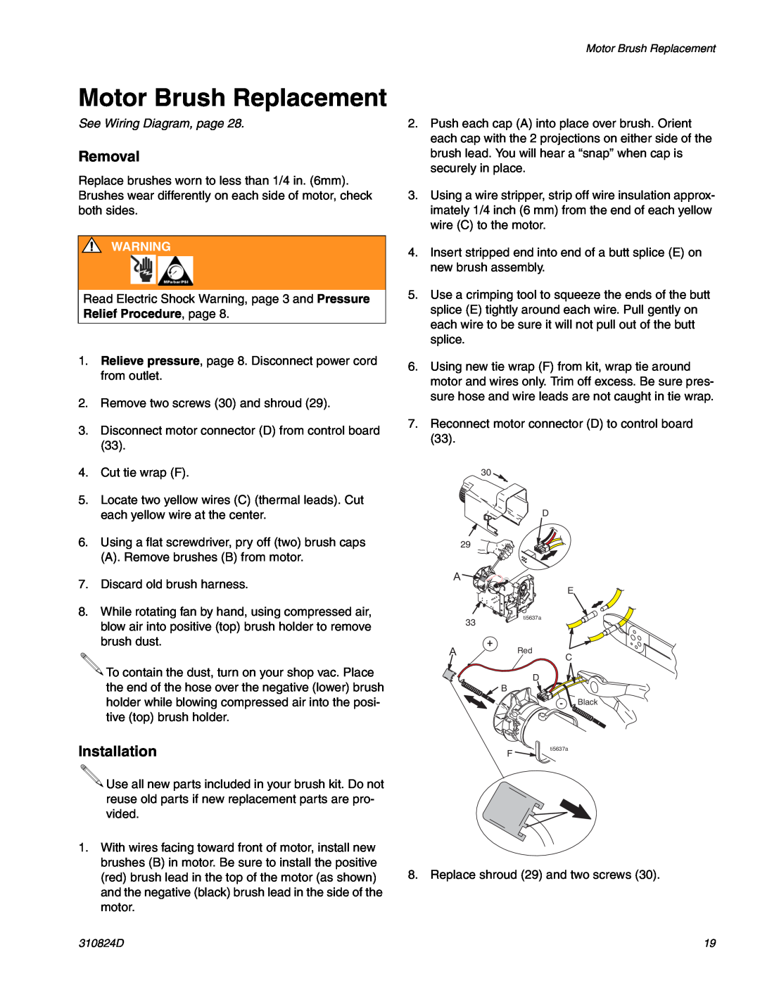
2.Remove two screws (30) and shroud (29).
3.Disconnect motor connector (D) from control board (33).
4.Cut tie wrap (F).
5.Locate two yellow wires (C) (thermal leads). Cut each yellow wire at the center.
6.Using a flat screwdriver, pry off (two) brush caps
(A). Remove brushes (B) from motor.
7.Discard old brush harness.
8.While rotating fan by hand, using compressed air, blow air into positive (top) brush holder to remove brush dust.
![]() To contain the dust, turn on your shop vac. Place
To contain the dust, turn on your shop vac. Place
Motor Brush Replacement
2.Push each cap (A) into place over brush. Orient each cap with the 2 projections on either side of the brush lead. You will hear a “snap” when cap is securely in place.
3.Using a wire stripper, strip off wire insulation approx- imately 1/4 inch (6 mm) from the end of each yellow wire (C) to the motor.
4.Insert stripped end into end of a butt splice (E) on new brush assembly.
5.Use a crimping tool to squeeze the ends of the butt splice (E) tightly around each wire. Pull gently on each wire to be sure it will not pull out of the butt splice.
6.Using new tie wrap (F) from kit, wrap tie around motor and wires only. Trim off excess. Be sure pres- sure hose and wire leads are not caught in tie wrap.
7.Reconnect motor connector (D) to control board (33).
30
D
29
A![]()
![]()
![]()
E
| 33 | ti5637a |
|
| |
A |
| + |
| Red | |
|
| C |
D
the end of the hose over the negative (lower) brush holder while blowing compressed air into the posi- tive (top) brush holder.
Installation
\![]()
![]()
![]()
![]() Use all new parts included in your brush kit. Do not reuse old parts if new replacement parts are pro- vided.
Use all new parts included in your brush kit. Do not reuse old parts if new replacement parts are pro- vided.
B
F
- Black
ti5637a
1.With wires facing toward front of motor, install new brushes (B) in motor. Be sure to install the positive (red) brush lead in the top of the motor (as shown) and the negative (black) brush lead in the side of the motor.
8. Replace shroud (29) and two screws (30).
310824D | 19 |