308584
INSTRUCTIONS-PARTS LIST
100 psi 0.7 MPa, 7 bar Maximum Working Pressure
Part No. 222700, Series C
Symbols
Table of Contents
Warning Symbol
Caution Symbol
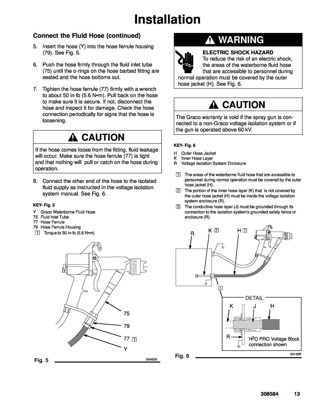
ELECTRIC SHOCK HAZARD
PRESSURIZED EQUIPMENT HAZARD
FIRE AND EXPLOSION HAZARD
Warnings are continued on the next page
TOXIC FLUID HAZARD
EQUIPMENT MISUSE HAZARD
Spraying Waterborne Fluids Electrostatically
Introduction
Operating the Electrostatics
Refer to Fig. 1, page
B A C
D Inner Hose Layer EE is a PTFE tube
Graco Waterborne Fluid Hose purchased separately
D Conductive Hose Layer DD covers the PTFE tube
H2O PRO Voltage Block connection shown
Installing the System
Installation
Ventilate the Spray Booth
Warning Signs
PRO 3500wb Gun shown with the Graco H2O PRO Batch System
Consult your isolation system manual for other configurations
T S N K L
M G F NH R B A E D P C
Install the Fluid LIne Accessories
Install the Air Line Accessories
Connect the Air Line
Connect the Exhaust Tube
Connect the Fluid Hose
Filter the Fluid
Continued on the next page
H2O PRO Voltage Block
Connect the Fluid Hose continued
connection shown
FIRE, EXPLOSION, AND ELECTRIC SHOCK HAZARD
Ground the System
Check the Electrical Grounding
Pressure Relief Procedure
Fluid Voltage Discharge and Grounding Procedure
Operation
Selecting a Fluid Nozzle and Air Cap
Operating Checklist
FIRE AND EXPLOSION HAZARD
Operating the Spray Gun
COMPONENT RUPTURE HAZARD
Fine Adjustments of the Spray Gun
Atomizing Air Valve Adjustment
Daily Care and Cleaning
Maintenance
Shutdown
Procedure
Clean the Air Cap and Fluid Nozzle
Flush the Spray Gun
Equipment needed
Voltage Loss Troubleshooting
Troubleshooting
Spray Gun
Waterborne Fluid Hose
Tests
Voltage Loss Troubleshooting continued
Problem
Electrical Troubleshooting
Solution
Cause
Spray Pattern Troubleshooting
Gun Operation Troubleshooting
Poor Electrostatic Wrap Troubleshooting
Gun Operation Troubleshooting continued
Test Gun Resistance
Electrical Tests
Test Resistor Stud Resistance
Test Power Supply Resistance
Prepare the Gun for Service
Service
Air Cap/Nozzle/Resistor Stud Replacement
Tools Included with the Gun
Installation
Air Cap/Nozzle/Resistor Stud Replacement continued
Electrode Needle Replacement
If installing the complete fluid rod assembly, go to step 11, page
Preventative Maintenance
Fluid Packing Rod Removal and Repair
Where
Fluid Packing Rod Removal and Repair continued
Fluid Adjustment Assembly Repair
Fan Air Adjustment Valve Repair
If installing the complete valve, go to step
DETAIL
Air Trigger Valve Repair
Fluid Adjustment Assembly Repair continued
� Apply a very light coat of lubricant to the o-rings 41
Atomizing Air Valve Repair
MOVING PARTS HAZARD
ES ON-OFF Valve Repair
05363B
Barrel Removal
� Apply a very light coat of lubricant to the o-rings 37a
Power Supply Replacement
� Do not expose the gasket 18a to solvents
Barrel Installation
Turbine Alternator Replacement
05158B
Measurements, inches mm
Graco Waterborne Fluid Hose Repair
NOTE Keep all the following parts for reassembly
PRO 3500SC Gun Disassembly
PRO 3500sc Gun Conversion
Installing the Fluid Needle Assembly
10. Tighten the nut 78* onto the ferrule housing
See Detail A
Spray Gun Parts
Part No. 222700, Series C Model PRO 3500wb Spray Gun
EQUIPMENT MISUSE HAZARD
Y Replacement Warning signs are available at no cost
Description
Use Only Genuine Graco Parts and Accessories
Accessories
Waterborne Fluid Hose Assembly
100 psi 0.7 MPa, 7 bar Maximum Working Pressure
Manual Change Summary
For use in the Fluid Voltage Discharge and Ground- ing Procedure
Snap Ring Pliers
Gun High Voltage Probe & Meter
Page
Category
Technical Data
Data
Graco Phone Number
The Graco Warranty and Disclaimers
WARRANTY
EQUIPMENT NOT COVERED BY GRACO WARRANTY