9.Slide the motor upward, and place the
10.Slide the motor down to rest on the
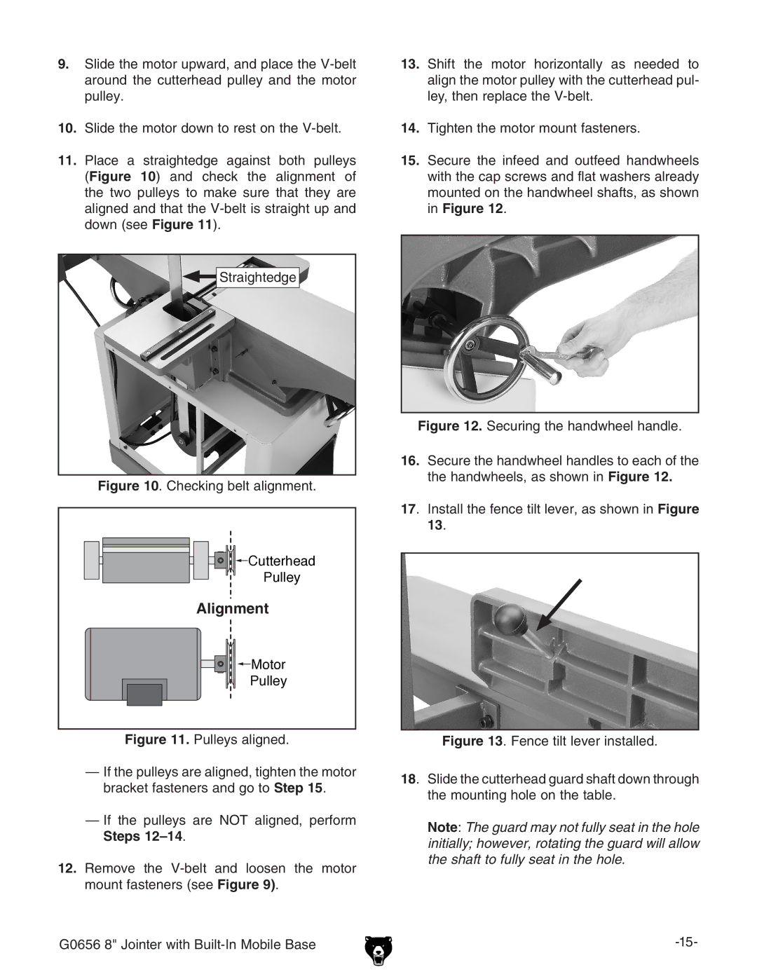
11.Place a straightedge against both pulleys (Figure 10) and check the alignment of the two pulleys to make sure that they are aligned and that the
Straightedge
Figure 10. Checking belt alignment.


 Cutterhead
Pulley
���������
 Motor
Motor
Pulley
Figure 11. Pulleys aligned.
—If the pulleys are aligned, tighten the motor bracket fasteners and go to Step 15.
—If the pulleys are NOT aligned, perform Steps 12–14.
12.Remove the V-belt and loosen the motor mount fasteners (see Figure 9).
13.Shift the motor horizontally as needed to align the motor pulley with the cutterhead pul- ley, then replace the V-belt.
14.Tighten the motor mount fasteners.
15.Secure the infeed and outfeed handwheels with the cap screws and flat washers already mounted on the handwheel shafts, as shown in Figure 12.
Figure 12. Securing the handwheel handle.
16.Secure the handwheel handles to each of the the handwheels, as shown in Figure 12.
17. Install the fence tilt lever, as shown in Figure 13.
Figure 13. Fence tilt lever installed.
18. Slide the cutterhead guard shaft down through the mounting hole on the table.
Note: The guard may not fully seat in the hole initially; however, rotating the guard will allow the shaft to fully seat in the hole.
G0656 8" Jointer with |
