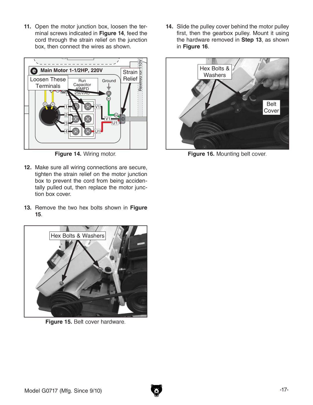
11.Open the motor junction box, loosen the ter- minal screws indicated in Figure 14, feed the cord through the strain relief on the junction box, then connect the wires as shown.
e | Main Motor | Strainfor110V | |||
Loosen These | Run | Ground | Relief | Rewired | |
Terminals | Capacitor |
|
| ||
40MFD |
|
| |||
|
| 250VAC |
|
|
|
| 1 |
| V1 |
|
|
| 2 |
| V1 |
|
|
|
|
|
|
| |
| 3 |
| U1 |
|
|
| 4 |
| U1 |
|
|
Figure 14. Wiring motor.
12.Make sure all wiring connections are secure, tighten the strain relief on the motor junction box to prevent the cord from being acciden- tally pulled out, then replace the motor junc- tion box cover.
13.Remove the two hex bolts shown in Figure 15.
Hex Bolts & Washers
Figure 15. Belt cover hardware.
14.Slide the pulley cover behind the motor pulley first, then the gearbox pulley. Mount it using the hardware removed in Step 13, as shown in Figure 16.
Hex Bolts &
Washers
Belt
Cover
Figure 16. Mounting belt cover.
Model G0717 (Mfg. Since 9/10) |
