Identification
A
B
C
L
K ![]()
M
D
Q
N ![]()
O ![]()
P![]()
E
F
G
H
I
J
|
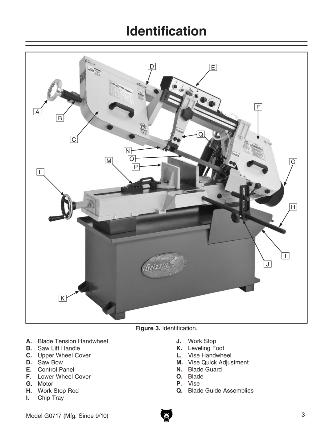
| Figure 3. Identification. | |
A. | Blade Tension Handwheel | J. | Work Stop |
B. | Saw Lift Handle | K. | Leveling Foot |
C. | Upper Wheel Cover | L. | Vise Handwheel |
D. | Saw Bow | M. | Vise Quick Adjustment |
E. | Control Panel | N. | Blade Guard |
F. | Lower Wheel Cover | O. | Blade |
G. | Motor | P. | Vise |
H. | Work Stop Rod | Q. | Blade Guide Assemblies |
I.Chip Tray
Model G0717 (Mfg. Since 9/10) |
