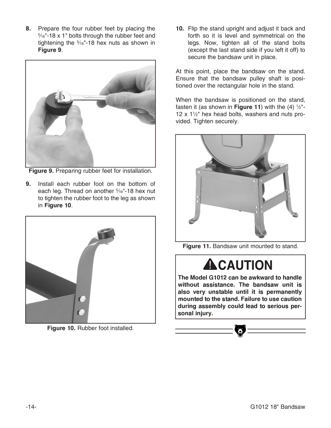
8.Prepare the four rubber feet by placing the
Figure 9.
Figure 9. Preparing rubber feet for installation.
9.Install each rubber foot on the bottom of each leg. Thread on another 5⁄16"-18 hex nut to tighten the rubber foot to the leg as shown in Figure 10.
Figure 10. Rubber foot installed.
10.Flip the stand upright and adjust it back and forth so it is level and symmetrical on the legs. Now, tighten all of the stand bolts (except the last stand side if you left it off) to secure the bandsaw unit in place.
At this point, place the bandsaw on the stand. Ensure that the bandsaw pulley shaft is posi- tioned over the rectangular hole in the stand.
When the bandsaw is positioned on the stand, fasten it (as shown in Figure 11) with the (4) 1⁄2"- 12 x 11⁄2" hex head bolts, washers and nuts pro- vided. Tighten securely.
Figure 11. Bandsaw unit mounted to stand.
The Model G1012 can be awkward to handle without assistance. The bandsaw unit is also very unstable until it is permanently mounted to the stand. Failure to use caution during assembly could lead to serious per- sonal injury.
G1012 18" Bandsaw |
