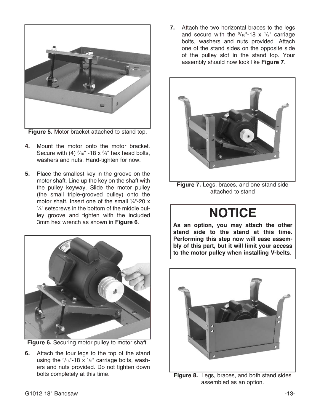
Figure 5. Motor bracket attached to stand top.
4.Mount the motor onto the motor bracket. Secure with (4) 5⁄16" -18 x 3⁄4" hex head bolts, washers and nuts. Hand-tighten for now.
5.Place the smallest key in the groove on the motor shaft. Line up the key on the shaft with the pulley keyway. Slide the motor pulley (the small triple-grooved pulley) onto the motor shaft. Insert one of the small 1⁄4"-20 x 1⁄4" setscrews in the bottom of the middle pul- ley groove and tighten with the included 3mm hex wrench as shown in Figure 6.
Figure 6. Securing motor pulley to motor shaft.
6.Attach the four legs to the top of the stand using the 5/16"-18 x 1/2" carriage bolts, wash- ers and nuts provided. Do not tighten down bolts completely at this time.
G1012 18" Bandsaw
7.Attach the two horizontal braces to the legs and secure with the 5/16"-18 x 1/2" carriage bolts, washers and nuts provided. Attach one of the stand sides on the opposite side of the pulley slot in the stand top. Your assembly should now look like Figure 7.
Figure 7. Legs, braces, and one stand side
attached to stand
NOTICE
As an option, you may attach the other stand side to the stand at this time. Performing this step now will ease assem- bly of this part, but it will limit your access to the motor pulley when installing