4-6 Installing Hardware Options
Accessing Other System Board
Components
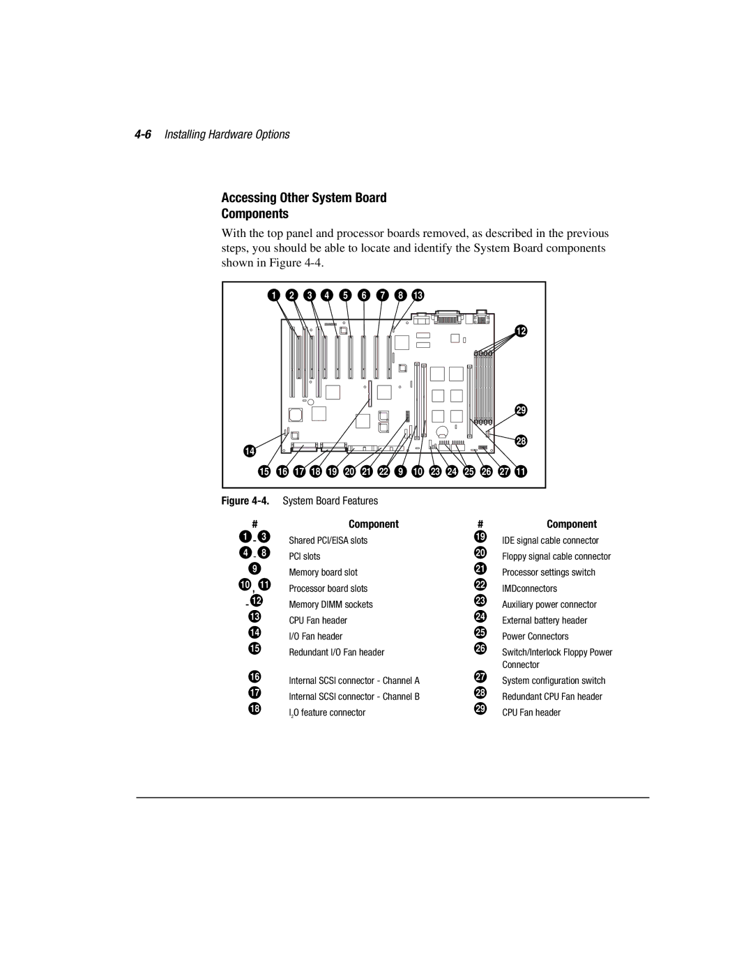
With the top panel and processor boards removed, as described in the previous steps, you should be able to locate and identify the System Board components shown in Figure
1 | 2 |
| 3 | 4 | 5 | 6 | 7 | 8 | 13 |
|
|
|
|
|
|
|
|
|
|
|
|
|
|
|
|
|
|
|
|
| 12 |
|
|
|
|
|
|
|
|
|
|
|
|
|
|
| 29 |
14 |
|
|
|
|
|
|
|
|
|
|
|
|
|
| 28 |
|
|
|
|
|
|
|
|
|
|
|
|
|
|
| |
15 | 16 | 17 | 18 | 19 | 20 | 21 | 22 | 9 | 10 | 23 | 24 | 25 | 26 | 27 | 11 |
Figure
#
1 - 3
4 - 8
9
10 , 11
- 12 13
14
15
16
17
18
System Board Features
Component
Shared PCI/EISA slots
PCI slots
Memory board slot
Processor board slots
Memory DIMM sockets
CPU Fan header
I/O Fan header
Redundant I/O Fan header
Internal SCSI connector - Channel A Internal SCSI connector - Channel B I2O feature connector
#Component
19IDE signal cable connector
20Floppy signal cable connector
21Processor settings switch
22IMDconnectors
23Auxiliary power connector
24External battery header
25Power Connectors
26Switch/Interlock Floppy Power Connector
27System configuration switch
28Redundant CPU Fan header
29CPU Fan header