Electrical Supply
![]() WARNING
WARNING
Electrical Shock Hazard
•Disconnect power before servicing.
•Replace all parts and panels before operating.
•Failure to do so can result in death or electrical shock.
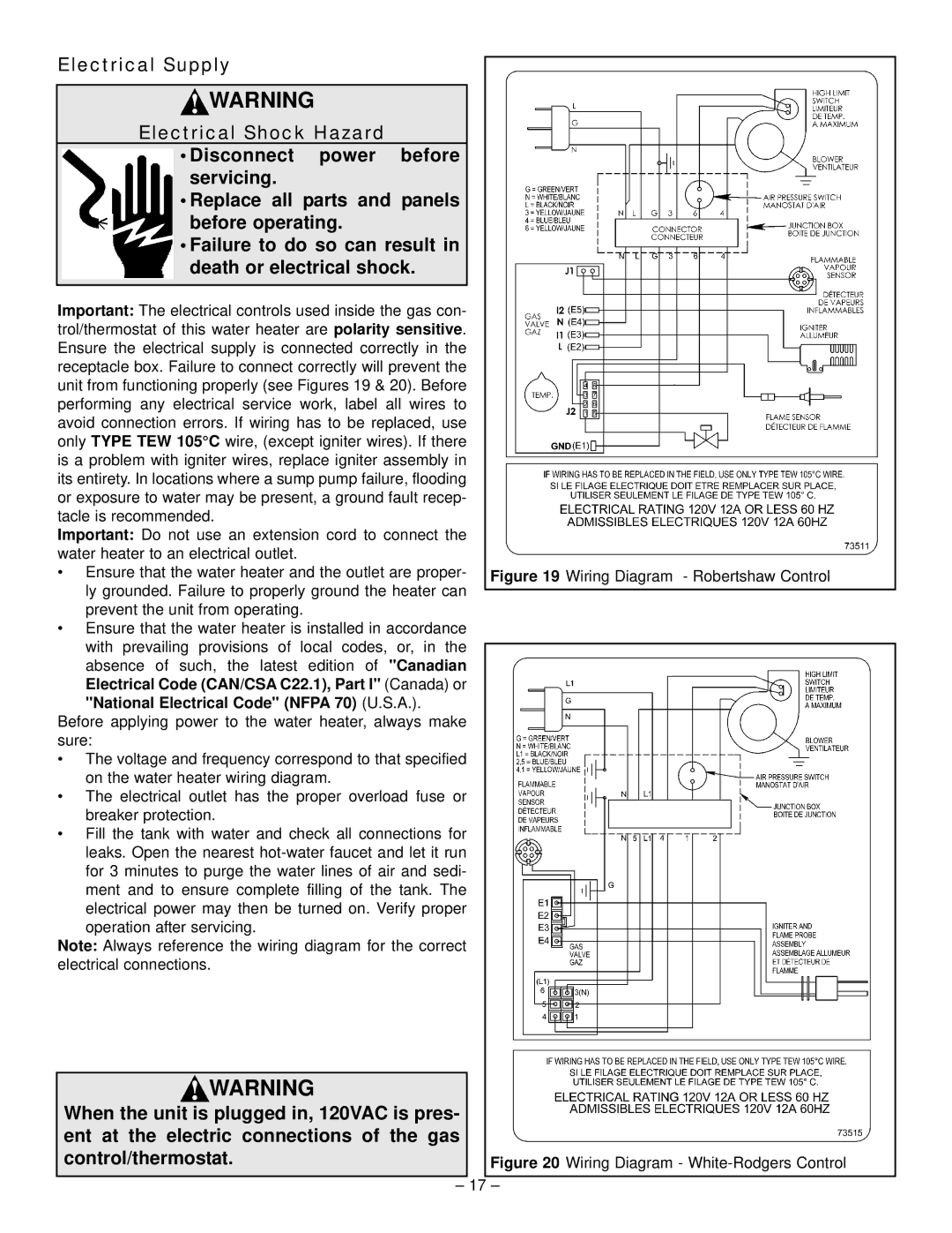
Important: The electrical controls used inside the gas con- trol/thermostat of this water heater are polarity sensitive. Ensure the electrical supply is connected correctly in the receptacle box. Failure to connect correctly will prevent the unit from functioning properly (see Figures 19 & 20). Before performing any electrical service work, label all wires to avoid connection errors. If wiring has to be replaced, use only TYPE TEW 105°C wire, (except igniter wires). If there is a problem with igniter wires, replace igniter assembly in its entirety. In locations where a sump pump failure, flooding or exposure to water may be present, a ground fault recep- tacle is recommended.
Important: Do not use an extension cord to connect the water heater to an electrical outlet.
• Ensure that the water heater and the outlet are proper- Figure 19 Wiring Diagram - Robertshaw Control ly grounded. Failure to properly ground the heater can
prevent the unit from operating.
•Ensure that the water heater is installed in accordance
with prevailing provisions of local codes, or, in the absence of such, the latest edition of "Canadian Electrical Code (CAN/CSA C22.1), Part I" (Canada) or "National Electrical Code" (NFPA 70) (U.S.A.).
Before applying power to the water heater, always make sure:
•The voltage and frequency correspond to that specified on the water heater wiring diagram.
•The electrical outlet has the proper overload fuse or breaker protection.
•Fill the tank with water and check all connections for
leaks. Open the nearest
Note: Always reference the wiring diagram for the correct electrical connections.
WARNING |
|
When the unit is plugged in, 120VAC is pres- |
|
ent at the electric connections of the gas |
|
control/thermostat. | Figure 20 Wiring Diagram - |
– 17 –