rounding area for damage and call a qualified service tech- |
|
| ||
nician to service the water heater and replace the flamma- |
|
| ||
ble vapour sensor. If there is a problem with the wiring of the | CALL FOR |
| ||
flammable vapour sensor or the flammable vapour interface |
| |||
HEAT |
| |||
the LED will flash the failure status code. |
| IGNITER IS | ||
|
|
| ENERGIZED AND MAIN | |
Resettable Lockout |
| VALVE IS OPENED | ||
|
| |||
The gas control/thermostat can be reset by unplugging the | CONTROL CHECKS TO | MAIN BURNER ON AND | ||
power cord to remove power and then reinserting the plug | ||||
ENSURE PRESSURE | ||||
THE FLAME IS | ||||
to restore the power. Robertshaw controls will automatically | SWITCH IS OPEN | |||
SENSED BY CONTROL | ||||
attempt to reset after a 20 minute wait period. White- |
|
| ||
Rodgers | BLOWER IS |
| ||
a 60 minute wait period. Also see "Troubleshooting Guide". | MAIN BURNER | |||
ENERGIZED | ||||
|
| CONTINUES TILL THE | ||
|
|
| ||
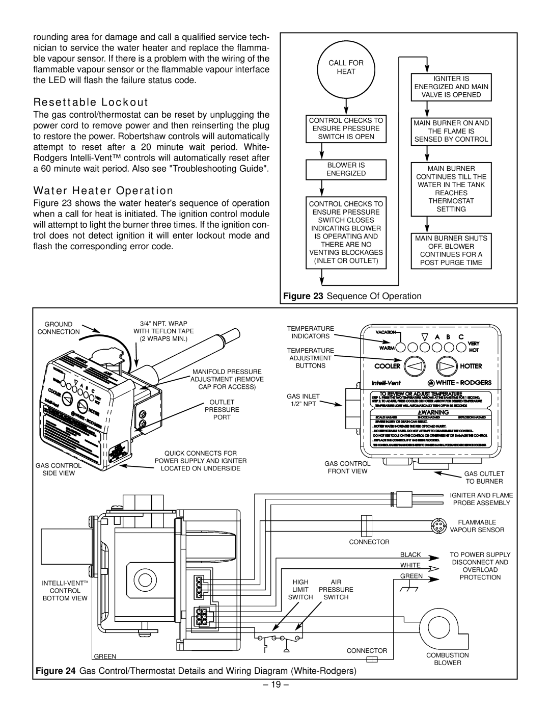
Water Heater Operation |
| WATER IN THE TANK | ||
| REACHES | |||
Figure 23 shows the water heater's sequence of operation | CONTROL CHECKS TO | THERMOSTAT | ||
when a call for heat is initiated. The ignition control module | ENSURE PRESSURE | SETTING | ||
will attempt to light the burner three times. If the ignition con- | SWITCH CLOSES |
| ||
INDICATING BLOWER |
| |||
trol does not detect ignition it will enter lockout mode and | IS OPERATING AND | MAIN BURNER SHUTS | ||
flash the corresponding error code. | THERE ARE NO | OFF. BLOWER | ||
|
| VENTING BLOCKAGES | CONTINUES FOR A | |
|
| (INLET OR OUTLET) | POST PURGE TIME | |
|
| Figure 23 Sequence Of Operation | ||
GROUND | 3/4” NPT. WRAP | TEMPERATURE |
| |
CONNECTION | WITH TEFLON TAPE |
| ||
INDICATORS |
| |||
| (2 WRAPS MIN.) |
| ||
|
|
| ||
|
| TEMPERATURE |
| |
|
| ADJUSTMENT |
| |
| MANIFOLD PRESSURE | BUTTONS |
| |
|
|
| ||
| ADJUSTMENT (REMOVE |
|
| |
| CAP FOR ACCESS) |
|
| |
| OUTLET | GAS INLET |
| |
| 1/2” NPT |
| ||
| PRESSURE |
|
| |
| PORT |
|
| |
| QUICK CONNECTS FOR |
|
| |
GAS CONTROL | POWER SUPPLY AND IGNITER | GAS CONTROL |
| |
LOCATED ON UNDERSIDE |
| |||
SIDE VIEW | FRONT VIEW | GAS OUTLET | ||
| ||||
|
|
| TO BURNER | |
|
|
| IGNITER AND FLAME | |
|
|
| PROBE ASSEMBLY | |
|
|
| FLAMMABLE | |
|
|
| VAPOUR SENSOR | |
|
| CONNECTOR |
| |
|
| BLACK | TO POWER SUPPLY | |
|
| WHITE | DISCONNECT AND | |
|
| OVERLOAD | ||
|
| GREEN | ||
HIGH | PROTECTION | |||
AIR |
| |||
CONTROL | LIMIT | PRESSURE |
| |
BOTTOM VIEW | SWITCH | SWITCH |
|
GREEN | CONNECTOR | COMBUSTION |
| ||
|
| BLOWER |
Figure 24 Gas Control/Thermostat Details and Wiring Diagram (White-Rodgers)
– 19 –