Anode Rod Replacement
To replace the anode:
1.Turn off gas supply to the water heater.
2.Shut off the water supply and open a nearby
3.Drain approximately 20 litres (5 US gallons) of water from tank (Refer to "Draining and Flushing" for proper procedures.) Close drain valve.
4.Remove old anode rod.
5.Use Teflon® tape or approved pipe sealant on threads and install new anode rod.
6.Turn on water supply and open nearby
7.Restart the water heater as directed under "Operating Your Water Heater." See the "Parts Reference Illustration" for anode rod location.
Routine Preventative Maintenance
Important: If you lack the necessary skills required to prop- erly perform this visual inspection, you should not proceed, but get help from a qualified service technician.
At least annually, a visual inspection should be made of the venting and air supply system, piping systems and main burner. Check the water heater for the following:
•Build up of soot and carbon on the main burner. Check for a soft blue flame.
•Leaking or damaged water and gas piping.
•Presence of flammable or corrosive materials in the installation area.
•Presence of combustible materials near the water heater.
•Verify proper operation after servicing this water heater.
Gas Control
There are no user serviceable parts in this control. The con- trol is supplied with tamper resistant screws. DO NOT attempt to repair or adjust the control. If you experience problems, discontinue use and replace the control immedi- ately. Continuing to use a damaged control could result in fire and/or explosion.
If you wish to verify that the water heater is operating prop- erly:
1.Make sure there is power to the water heater.
2.Make sure that the gas is turned on to the water heater.
3.Initiate a call for heat by either drawing hot water from a nearby faucet or raising the temperature setting (see section “Temperature Regulation”).
4.Note any error codes that appear and proceed to the “Troubleshooting” section.
Temperature and Pressure Relief Valve
![]() WARNING
WARNING
Explosion Hazard
•If the temperature and pressure relief valve is dripping or leaking, have a licensed plumber repair it.
•Do not plug valve.
•Do not remove valve.
•Failure to follow these instructions can result in death or an explosion.
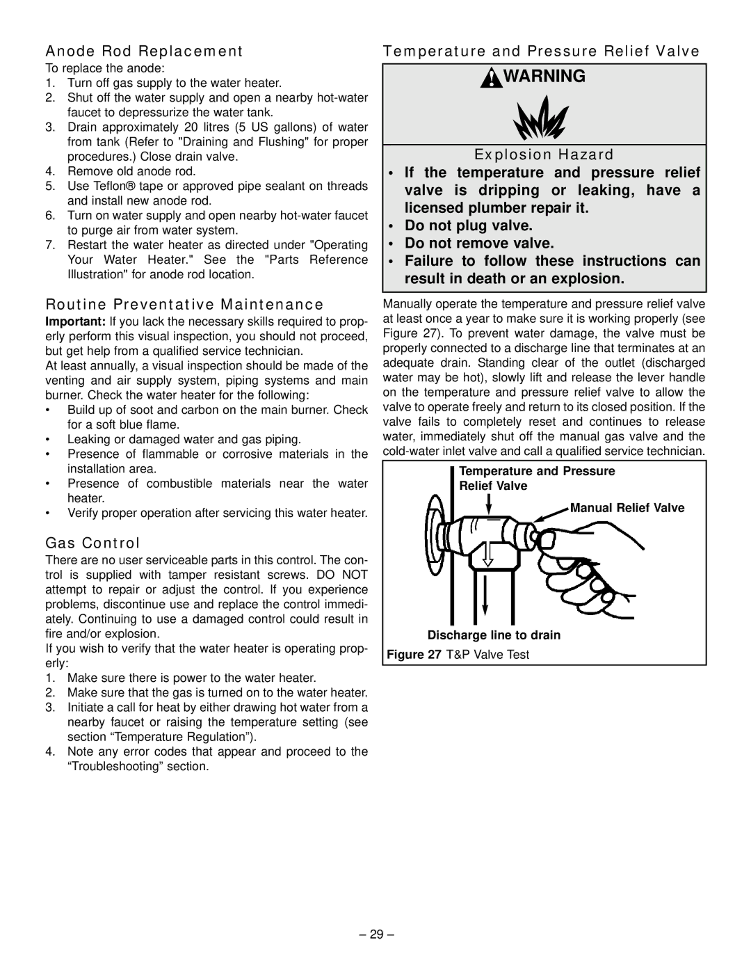
Manually operate the temperature and pressure relief valve at least once a year to make sure it is working properly (see Figure 27). To prevent water damage, the valve must be properly connected to a discharge line that terminates at an adequate drain. Standing clear of the outlet (discharged water may be hot), slowly lift and release the lever handle on the temperature and pressure relief valve to allow the valve to operate freely and return to its closed position. If the valve fails to completely reset and continues to release water, immediately shut off the manual gas valve and the
Temperature and Pressure
Relief Valve
Manual Relief Valve
Discharge line to drain
Figure 27 T&P Valve Test
– 29 –