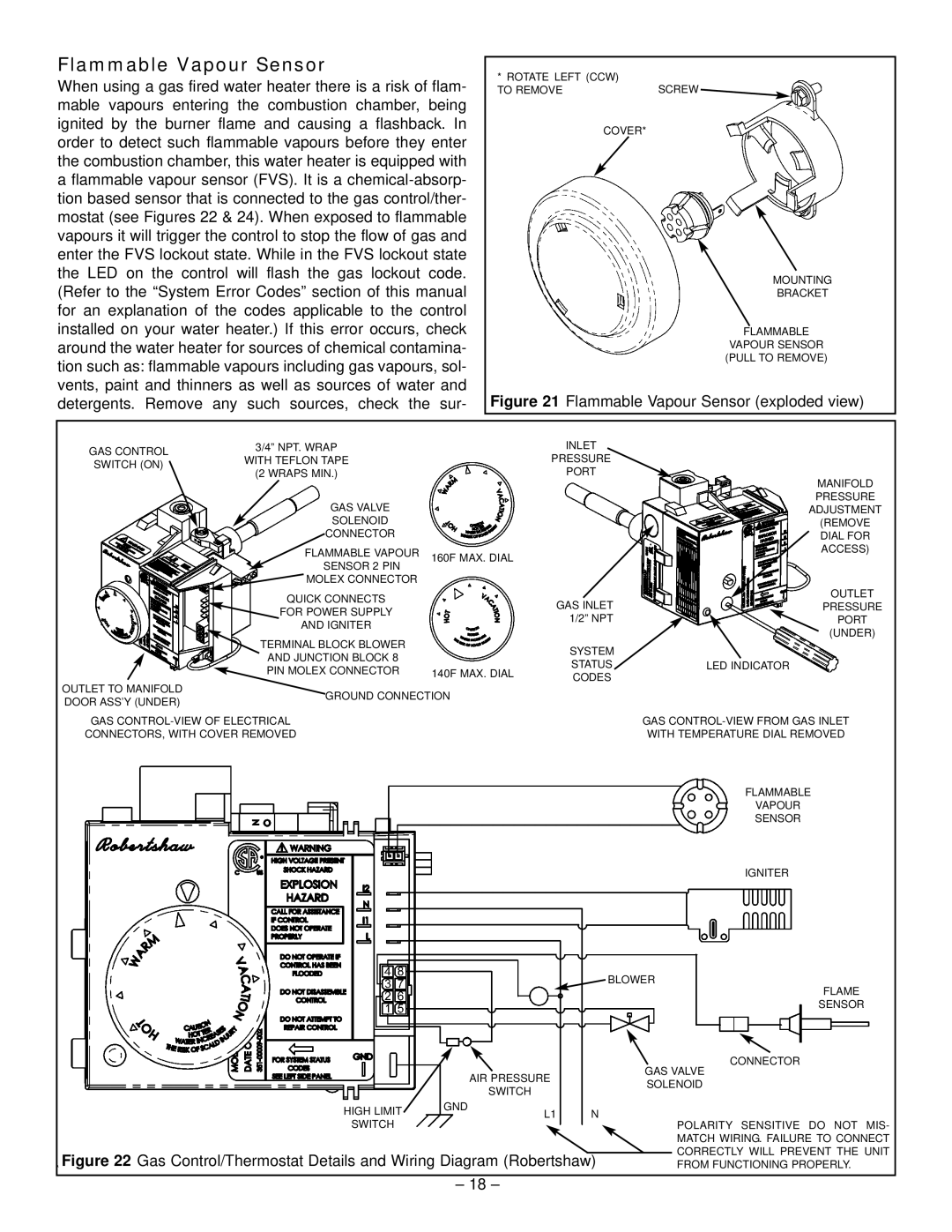
Flammable Vapour Sensor
When using a gas fired water heater there is a risk of flam- mable vapours entering the combustion chamber, being ignited by the burner flame and causing a flashback. In order to detect such flammable vapours before they enter the combustion chamber, this water heater is equipped with a flammable vapour sensor (FVS). It is a
* ROTATE LEFT (CCW) | SCREW |
TO REMOVE | |
COVER* |
|
MOUNTING
BRACKET
FLAMMABLE
VAPOUR SENSOR (PULL TO REMOVE)
Figure 21 Flammable Vapour Sensor (exploded view)
GAS CONTROL
SWITCH (ON)
3/4” NPT. WRAP
WITH TEFLON TAPE
(2 WRAPS MIN.)
INLET
PRESSURE
PORT
GAS VALVE
SOLENOID
CONNECTOR
FLAMMABLE VAPOUR
SENSOR 2 PIN
160F MAX. DIAL
MANIFOLD PRESSURE ADJUSTMENT (REMOVE DIAL FOR ACCESS)
![]() MOLEX CONNECTOR
MOLEX CONNECTOR
QUICK CONNECTS
![]() FOR POWER SUPPLY AND IGNITER
FOR POWER SUPPLY AND IGNITER
TERMINAL BLOCK BLOWER
AND JUNCTION BLOCK 8
PIN MOLEX CONNECTOR
| GAS INLET | OUTLET |
| PRESSURE | |
| 1/2” NPT | PORT |
|
| (UNDER) |
| SYSTEM |
|
140F MAX. DIAL | STATUS | LED INDICATOR |
CODES |
| |
|
|
OUTLET TO MANIFOLD DOOR ASS’Y (UNDER)
GROUND CONNECTION
GAS
CONNECTORS, WITH COVER REMOVED
AIR PRESSURE
SWITCH
HIGH LIMIT | GND | L1 | N |
|
SWITCH
Figure 22 Gas Control/Thermostat Details and Wiring Diagram (Robertshaw)
GAS
WITH TEMPERATURE DIAL REMOVED
FLAMMABLE
VAPOUR
SENSOR
IGNITER
BLOWER
FLAME
SENSOR
CONNECTOR
GAS VALVE
SOLENOID
POLARITY SENSITIVE DO NOT MIS- MATCH WIRING. FAILURE TO CONNECT CORRECTLY WILL PREVENT THE UNIT FROM FUNCTIONING PROPERLY.
– 18 –