CAUTION:
Read before proceeding. If you do not follow these instructions exactly, a fire or explosion may result, causing property damage, per- sonal injury or loss of life.
Gas Control/Thermostat
Alternatively, this heater may be equipped with the White- Rodgers
This heater is equipped with a
Putting the Heater into Service
1.Turn the manual gas
2.Follow the Lighting Instructions
3.Upon start up all the indicator lights on the front of the control will come on and then turn off. This indicates that the control has completed a
Note: If any of the indicator lights remain on, this indicates a system fault that needs correcting. See the “System Error Codes” and “Troubleshooting Guide
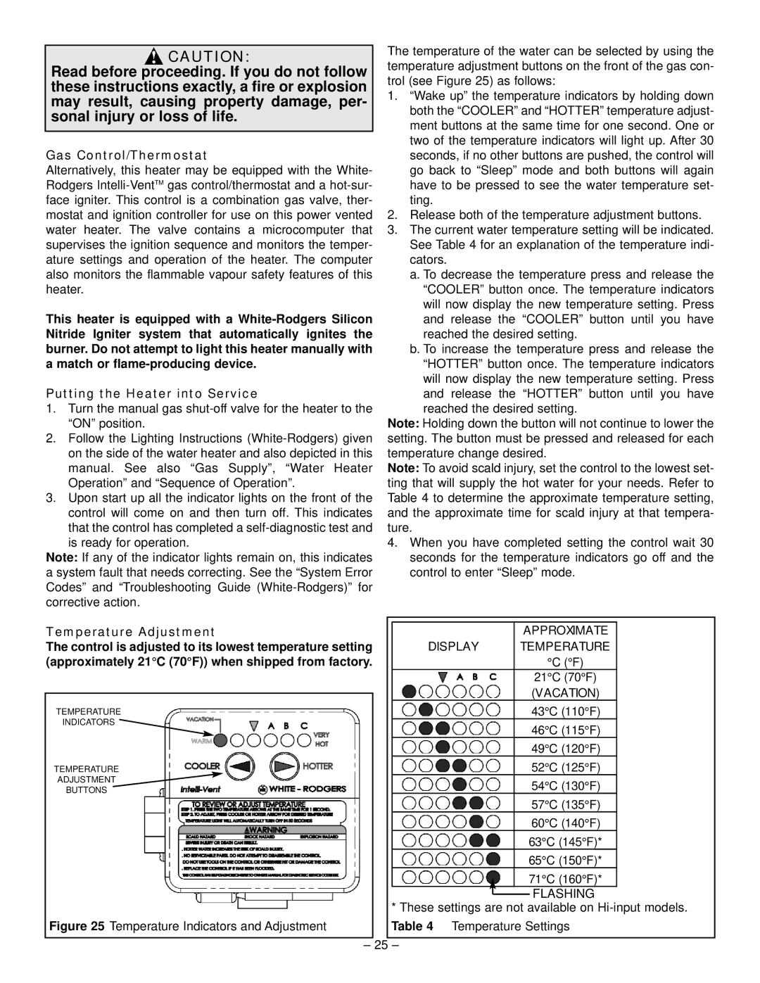
The temperature of the water can be selected by using the temperature adjustment buttons on the front of the gas con- trol (see Figure 25) as follows:
1.“Wake up” the temperature indicators by holding down both the “COOLER” and “HOTTER” temperature adjust- ment buttons at the same time for one second. One or two of the temperature indicators will light up. After 30 seconds, if no other buttons are pushed, the control will go back to “Sleep” mode and both buttons will again have to be pressed to see the water temperature set- ting.
2.Release both of the temperature adjustment buttons.
3.The current water temperature setting will be indicated. See Table 4 for an explanation of the temperature indi- cators.
a.To decrease the temperature press and release the “COOLER” button once. The temperature indicators will now display the new temperature setting. Press and release the “COOLER” button until you have reached the desired setting.
b.To increase the temperature press and release the “HOTTER” button once. The temperature indicators will now display the new temperature setting. Press and release the “HOTTER” button until you have reached the desired setting.
Note: Holding down the button will not continue to lower the setting. The button must be pressed and released for each temperature change desired.
Note: To avoid scald injury, set the control to the lowest set- ting that will supply the hot water for your needs. Refer to Table 4 to determine the approximate temperature setting, and the approximate time for scald injury at that tempera- ture.
4.When you have completed setting the control wait 30 seconds for the temperature indicators go off and the control to enter “Sleep” mode.
Temperature Adjustment | DISPLAY | APPROXIMATE | |
The control is adjusted to its lowest temperature setting | TEMPERATURE | ||
(approximately 21°C (70°F)) when shipped from factory. |
| °C (°F) | |
|
|
| 21°C (70°F) |
|
|
| (VACATION) |
|
|
| |
TEMPERATURE |
| 43°C (110°F) | |
INDICATORS |
| 46°C (115°F) | |
|
|
| |
|
|
| 49°C (120°F) |
TEMPERATURE |
| 52°C (125°F) | |
ADJUSTMENT |
| 54°C (130°F) | |
BUTTONS |
| ||
|
|
| 57°C (135°F) |
|
|
| 60°C (140°F) |
|
|
| 63°C (145°F)* |
|
|
| 65°C (150°F)* |
|
|
| 71°C (160°F)* |
![]() FLASHING
FLASHING
* These settings are not available on
Figure 25 Temperature Indicators and Adjustment |
|
| Table 4 Temperature Settings |
|
| 25 |
|
| – | – |