Installation Procedure
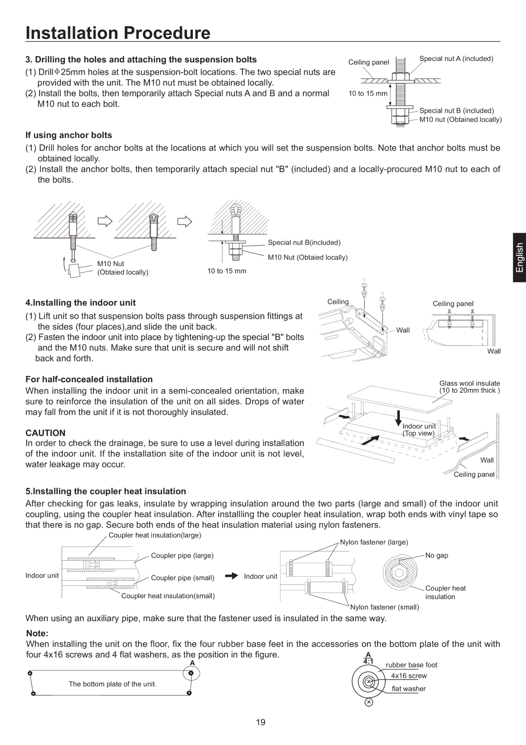
3. Drilling the holes and attaching the suspension bolts
(1)Drill ![]() 25mm holes at the
25mm holes at the
(2)Install the bolts, then temporarily attach Special nuts A and B and a normal M10 nut to each bolt.
Bolt strength: 980 to 1470 N (100 TO 150 kgf)
If using anchor bolts
Ceiling panel | Special nut A (included) |
|
10 to 15 mm
Special nut B (included)
M10 nut (Obtained locally)
(1)Drill holes for anchor bolts at the locations at which you will set the suspension bolts. Note that anchor bolts must be obtained locally.
(2)Install the anchor bolts, then temporarily attach special nut "B" (included) and a
| Special nut B(included) | |
M10 Nut | M10 Nut (Obtaied locally) | |
10 to 15 mm | ||
(Obtaied locally) |
4.Installing the indoor unit | Ceiling |
(1)Lift unit so that suspension bolts pass through suspension fittings at the sides (four places),and slide the unit back.
(2) Fasten the indoor unit into place by
For half-concealed installation
When installing the indoor unit in a
CAUTION
In order to check the drainage, be sure to use a level during installation of the indoor unit. If the installation site of the indoor unit is not level, water leakage may occur.
Ceiling panel
Wall
Wall
Glass wool insulate (10 to 20mm thick )
![]() Indoor unit (Top view)
Indoor unit (Top view)
Wall
Ceiling panel
5.Installing the coupler heat insulation
After checking for gas leaks, insulate by wrapping insulation around the two parts (large and small) of the indoor unit coupling, using the coupler heat insulation. After installling the coupler heat insulation, wrap both ends with vinyl tape so that there is no gap. Secure both ends of the heat insulation material using nylon fasteners.
| Coupler heat insulation(large) | Nylon fastener (large) |
|
| |
| Coupler pipe (large) | No gap |
Indoor unit | Coupler pipe (small) | Indoor unit |
![]() Coupler heat
Coupler heat
Coupler heat insulation(small)insulation
Nylon fastener (small)
When using an auxiliary pipe, make sure that the fastener used is insulated in the same way.
Note:
When installing the unit on the floor, fix the four rubber base feet in the accessories on the bottom plate of the unit with
four 4x16 screws and 4 flat washers, as the position in the figure. | A | |
A | 4:1 rubber base foot | |
The bottom plate of the unit. | 4x16 screw | |
flat washer | ||
|
19
